APPLICATIONS OF IMAGE INTERFERENCE
Although the information brought out by image interference between lighting
modes, colour channels, and so on is often significant and useful, the
application of these techniques must be done with care. Visual artifacts may be
created, not only because Adobe Photoshop’s “Difference” blending mode, as
mentioned, renders all subtraction results of pixel values positive, but also
because the signal intensity in each image results from interactions of a number
of factors (colour, morphology, reflectance, spectrum and angle of incident
light, etc.). When several complex signals are combined the results become more
difficult to interpret.
 Nonetheless,
when the difference between the images is pronounced and due to only one or a
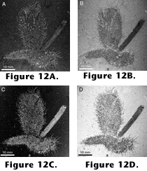
few factors, image interference may yield spectacular results. Figure
12 shows an assemblage of fossils, two chancelloriids and one sponge from
the Burgess Shale, photographed under water without (Figure
12A) and with (Figure 12B) crossed
nicols. The chancelloriids have three distinct types of tissue preservation:
sclerites preserved in pyrite (bright in both Figures 12A
and 12B), sclerites preserved as a
shiny film (semibright in Figure 12A,
dark in Figure 12B), and integument
preserved as a nonshiny film (same colour as matrix in Figure
12A, darker than the matrix in Figure
12B). When Figure 12B (with
its darker fossil relative to the matrix) is subtracted from Figure
12A (with its lighter fossil), the brightness gap between the films (most
sclerites and integument; the pyritized sclerites acquire a brightness
intermediate between matrix and films) comes out in bright pixels, contrasting
sharply with the dark matrix (Figure 12C;
cf. also Figure 10A–B, E–F, in
which the central part of the picture acquires higher pixel values after the
subtraction).
Nonetheless,
when the difference between the images is pronounced and due to only one or a
few factors, image interference may yield spectacular results. Figure
12 shows an assemblage of fossils, two chancelloriids and one sponge from
the Burgess Shale, photographed under water without (Figure
12A) and with (Figure 12B) crossed
nicols. The chancelloriids have three distinct types of tissue preservation:
sclerites preserved in pyrite (bright in both Figures 12A
and 12B), sclerites preserved as a
shiny film (semibright in Figure 12A,
dark in Figure 12B), and integument
preserved as a nonshiny film (same colour as matrix in Figure
12A, darker than the matrix in Figure
12B). When Figure 12B (with
its darker fossil relative to the matrix) is subtracted from Figure
12A (with its lighter fossil), the brightness gap between the films (most
sclerites and integument; the pyritized sclerites acquire a brightness
intermediate between matrix and films) comes out in bright pixels, contrasting
sharply with the dark matrix (Figure 12C;
cf. also Figure 10A–B, E–F, in
which the central part of the picture acquires higher pixel values after the
subtraction).
Subtracting channel A from B, the inverse picture is obtained (Figure
12D; cf. Figure 10E–F vs. G–H).
Such a negative image is most easily produced directly through the “Inverse”
command in Adobe Photoshop and may turn up to be better for viewing details than
the positive image (compare the frequent use of negative images in astronomy).
An Adobe Photoshop PSD file
(1.8 MB), containing the original colour images (in reduced resolution) for Figure
12, is enclosed to enable the reader to experiment with layer and channel
interference.
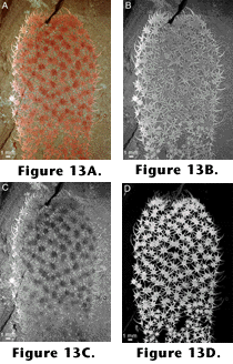 Another
example of the same image interference technique is between colour channels of
one colour picture. Figure 13A shows a
specimen of Chancelloria from the Middle Cambrian Wheeler Shale of Utah.
The sclerites are spectacularly preserved in limonite (presumably arising from
the weathering of pyrite) and would seem to need no enhancement. Crossed nicols
are often applied with advantage on this material, as in this picture, because
the rock is a friable mudstone that often does not survive immersion in liquid.
Nonetheless, the sclerites form an intricate meshwork, and many rays are
indistinct because they are somewhat buried and lie under a very thin layer of
matrix. By subtracting the green channel (Figure
13C) from the red one (Figure 13B),
we achieve a highly enhanced contrast between sclerites and matrix, making the
bright sclerites appear as if they were suspended over a black background (Figure
13D). The uneven colouring of the central versus peripheral sclerites in the
original picture (Figure 13A) has
disappeared in the final image, because the procedure singles out spectral
colour differences rather than differences in intensity. As the sclerites lie in
several layers, a three-dimensional effect obtains. The result could not have
been achieved simply by enhancing the contrast of the red channel.
Another
example of the same image interference technique is between colour channels of
one colour picture. Figure 13A shows a
specimen of Chancelloria from the Middle Cambrian Wheeler Shale of Utah.
The sclerites are spectacularly preserved in limonite (presumably arising from
the weathering of pyrite) and would seem to need no enhancement. Crossed nicols
are often applied with advantage on this material, as in this picture, because
the rock is a friable mudstone that often does not survive immersion in liquid.
Nonetheless, the sclerites form an intricate meshwork, and many rays are
indistinct because they are somewhat buried and lie under a very thin layer of
matrix. By subtracting the green channel (Figure
13C) from the red one (Figure 13B),
we achieve a highly enhanced contrast between sclerites and matrix, making the
bright sclerites appear as if they were suspended over a black background (Figure
13D). The uneven colouring of the central versus peripheral sclerites in the
original picture (Figure 13A) has
disappeared in the final image, because the procedure singles out spectral
colour differences rather than differences in intensity. As the sclerites lie in
several layers, a three-dimensional effect obtains. The result could not have
been achieved simply by enhancing the contrast of the red channel.
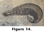 Whenever
a colour difference exists in a picture, it may be enhanced by this procedure.
The picture of Yunnanozoon (Figure 6),
in addition to the typical reddish tint, has bluish areas marking out the
tissues surrounding the gut. By subtracting the blue channel from the green one,
the bluish areas were enhanced by darkening; the resulting channel was then
blended with the original colour image (using Adobe Photoshop’s “Multiply”
mode, which has the same effect as superimposing the images upon each other) to
get back to a more natural-looking image (Figure
14).
Whenever
a colour difference exists in a picture, it may be enhanced by this procedure.
The picture of Yunnanozoon (Figure 6),
in addition to the typical reddish tint, has bluish areas marking out the
tissues surrounding the gut. By subtracting the blue channel from the green one,
the bluish areas were enhanced by darkening; the resulting channel was then
blended with the original colour image (using Adobe Photoshop’s “Multiply”
mode, which has the same effect as superimposing the images upon each other) to
get back to a more natural-looking image (Figure
14).
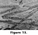 In
In
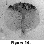 the
case of the graptolite image in Figure 8,
subtraction of the green channel of the
image taken under crossed nicols (Figure
8B) from that of the unpolarized image (Figure
8A) enhances the carbonized structures of the graptolite rhabdosomes and
brings out features that were obscure in the original image (Figure
15). Subtracting the green channel of the original picture of Burgessia
(Figure 5A) from the red one in the
image taken under crossed nicols (Figure 5B)
simultaneously brings out structures in the darkest and the lighter parts of the
original images (Figure 16).
the
case of the graptolite image in Figure 8,
subtraction of the green channel of the
image taken under crossed nicols (Figure
8B) from that of the unpolarized image (Figure
8A) enhances the carbonized structures of the graptolite rhabdosomes and
brings out features that were obscure in the original image (Figure
15). Subtracting the green channel of the original picture of Burgessia
(Figure 5A) from the red one in the
image taken under crossed nicols (Figure 5B)
simultaneously brings out structures in the darkest and the lighter parts of the
original images (Figure 16).