FIGURE 1. Posterior view of CV 12 showing brittle (arrow) and plastic deformation (lines; indicate the originally horizontal plane of postzygapophyses (above) and transverse processes (below)). Scale bar equals 5 cm.
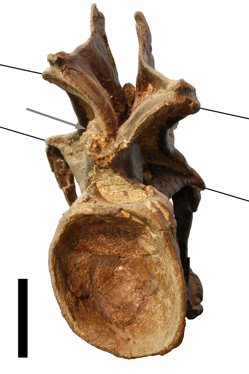
FIGURE 2. Landmarks used for the retrodeformation methods, shown in CV 10 in posterior, right lateral, and anterior view (from left to right). Only landmarks on right side are shown. The landmarks on the centrum are: 1) anteromedial corners of the parapophyses; 2) posterior ends of the parapophyses; 3) dorsolateral corner of the border of the cotyle, where the centropostzygapophyseal laminae converge with the centrum; 4) ventrolateral corner of the cotyle, where the posterolateral flanges of the ventral surface of the centrum merge with the border of the cotyle. The landmarks on the neural arch are: 5) anterior ends of prezygadiapophyseal laminae; 6) anterior-most points of prezygapophyses; 7) medial-most point of prezygapophyses; 8) medial sides of insertion of centroprezygapophyseal laminae into prezygapophyses; 9) posterolateral-most points of transverse processes; 10) anterior-most points of the neural spine summit; 11) small protrusions at the center of the neural spine summit; 12) posterior-most point of the neural spine summit; 13) posteromedial corners of postzygapophyses; 14) anterolateral corners of postzygapophyses; 15) posterior ends of spinopostzygapophyseal laminae. The landmark on the cervical rib is its anterior-most tip (16).
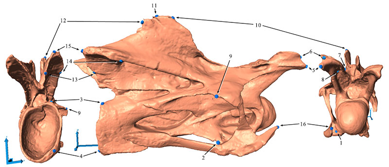
FIGURE 3. Shape changes after two retrodeformation steps in CV 12 in dorsal (A), anterior (B), and left lateral (C) view. The full shape marks the original deformed model, the outlines show the shape of the retrodeformed models (green: SAM, dark and light red: MM, two steps).
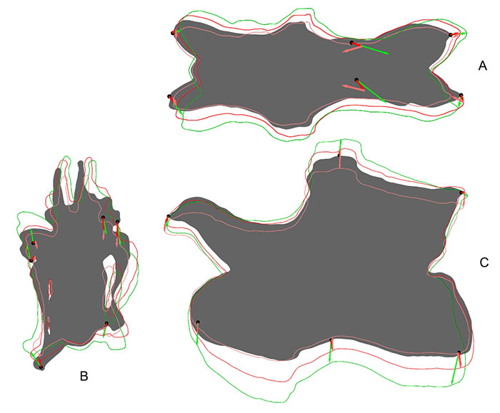
FIGURE 4. Outlines of different retrodeformed models of CV 12 obtained by using 4 (green), 9 (blue), or 16 (red) landmarks to define the midsagittal plane. A: results of the MM, B: results of the SAM.
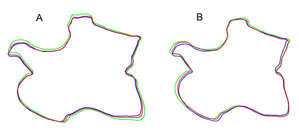
FIGURE 5. Original and retrodeformed models of CV 10 in dorsal (top left), anterior (bottom left), and lateral view (right). Note the elongation of the prezygapophysis in the retrodeformed models (arrow) and the slenderness of the model produced by the MM. Vertebrae not to scale.
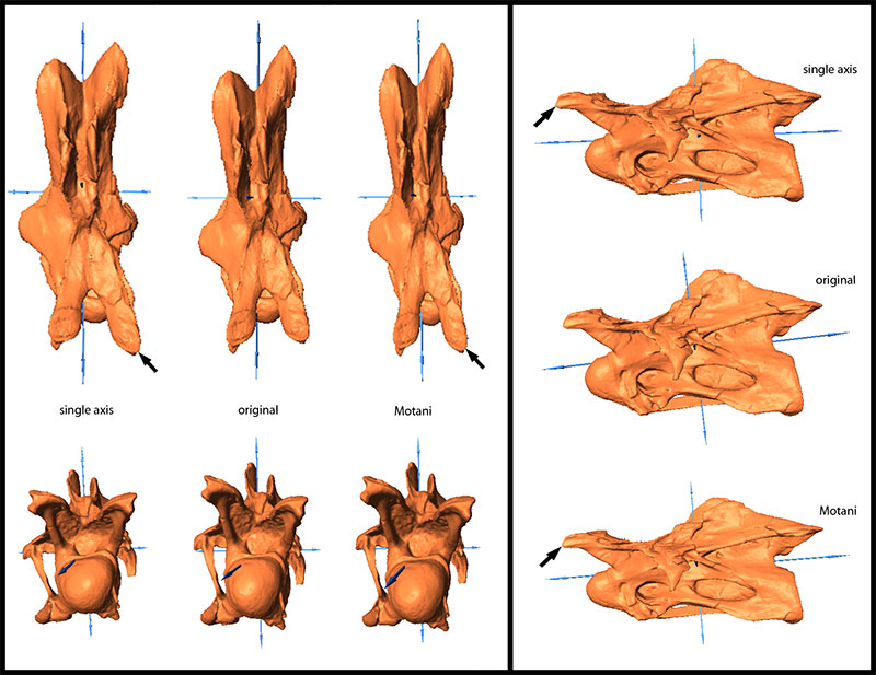
FIGURE 6. Original and retrodeformed models of CV 11 in dorsal (top left), anterior (bottom left), and lateral view (right). Note the levelling of the transverse processes in the retrodeformed models (arrows). Vertebrae not to scale.
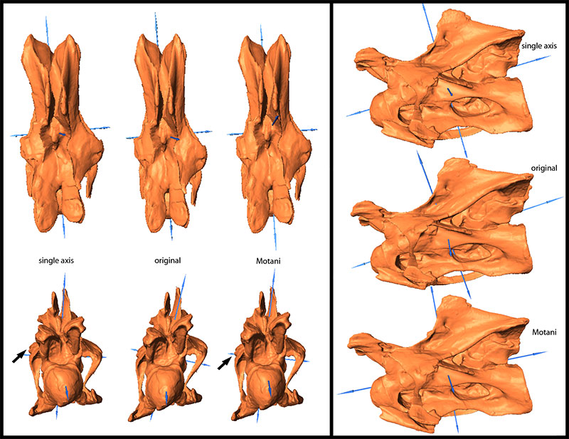
FIGURE 7. Original and retrodeformed models of CV 12 in dorsal (top left), anterior (bottom left), and lateral view (right). Note the more rounded condyles (arrows) and the pronounced robustness of the model produced by the SAM. Vertebrae not to scale.
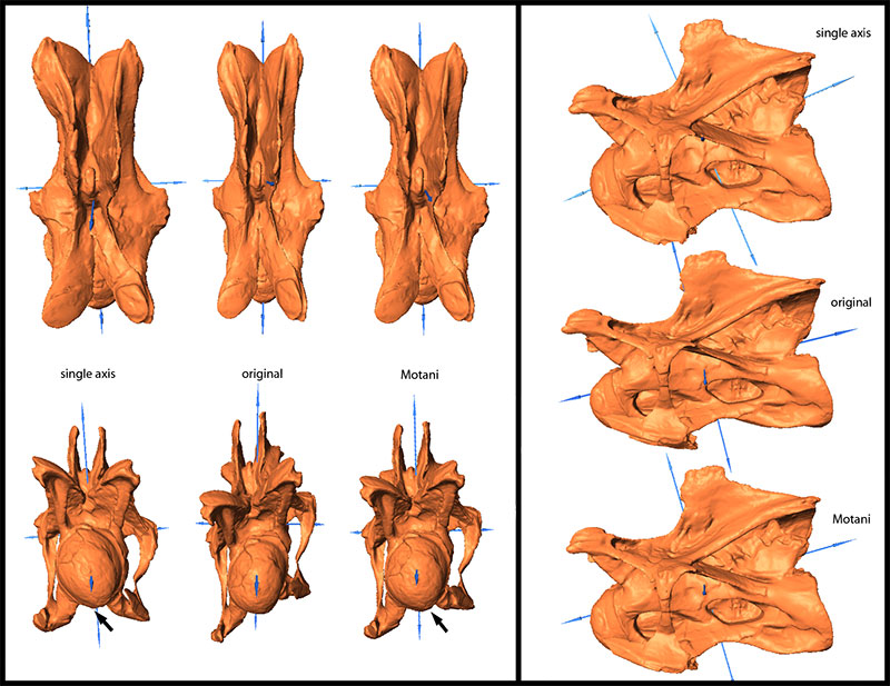
FIGURE 8. Original and retrodeformed models of CV 13 in dorsal (top left), anterior (bottom left), and lateral view (right). Note the more pronounced posteroventral corner in the SAM (arrow). Vertebrae not to scale.
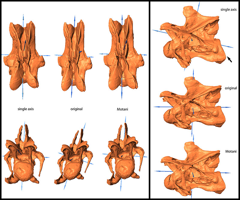
FIGURE 9. Original and retrodeformed models of CV 14 in dorsal (top left), anterior (bottom left), and lateral view (right). Note the retraction of the prezygapophyses in the retrodeformed models (arrows) and the robustness of the model produced by the SAM. Vertebrae not to scale.
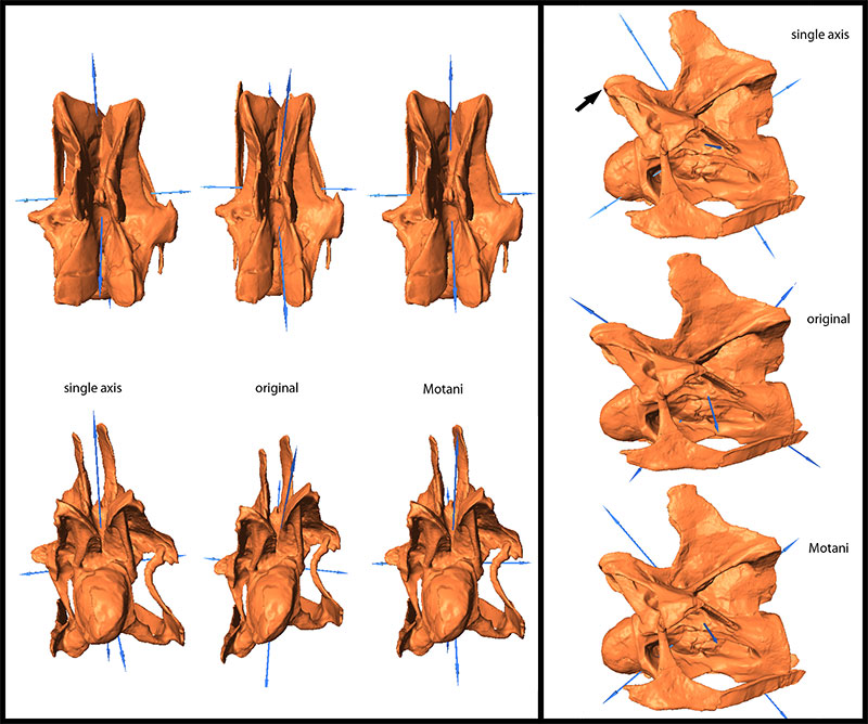
FIGURE 10. Original, deformed (using compression), and retrodeformed models of a cervical vertebra of Raphus cucullatus (DNSM Ornithology 2366) in anterior (top), right lateral (center), and dorsal (bottom) view. Note the transversely more compressed retrodeformed models compared to the deformed model.
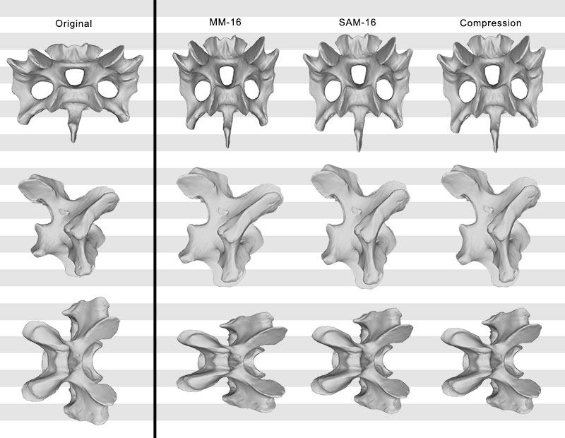
FIGURE 11. Original, deformed (using shear), and retrodeformed models of a cervical vertebra of Raphus cucullatus (DNSM Ornithology 2366) in anterior (top), right lateral (center), and dorsal (bottom) view. Note the dorsoventrally more compressed retrodeformed models compared to the deformed model.
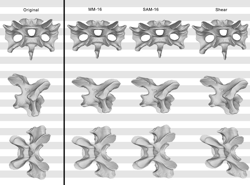
FIGURE 12. Original, deformed (compression and shear combined), and retrodeformed models of a cervical vertebra of Raphus cucullatus (DNSM Ornithology 2366) in anterior (top), right lateral (center), and dorsal (bottom) view. Note the dorsoventrally higher, and anteroposteriorly shorter retrodeformed models compared to the deformed model.
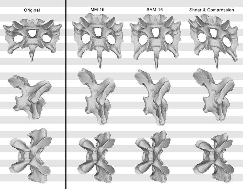
FIGURE 13. Phylogenetic trees (based on Harris, 2006) recovered with (left) and without (right) the questionable characters (H112 and H114). Bootstrap values indicated if > 50. Note the better resolved tree without the questionable characters. Bootstrap values in the right tree are higher for high-level, but lower for low-level taxa.
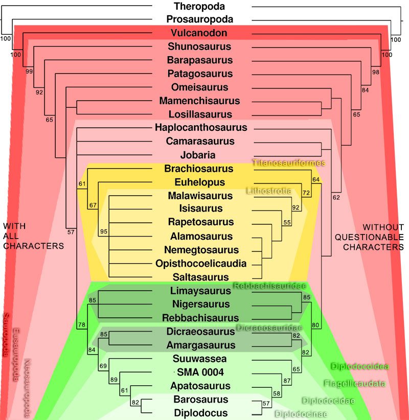
FIGURE 14. Phylogenetic trees (based on Whitlock, 2011) recovered with (left) and without (right) the questionable character (W90). Bootstrap values indicated if > 50. Note the differences in diplodocine intrarelationships. Bootstrap values in the right tree are higher for high-level, but lower for low-level taxa.
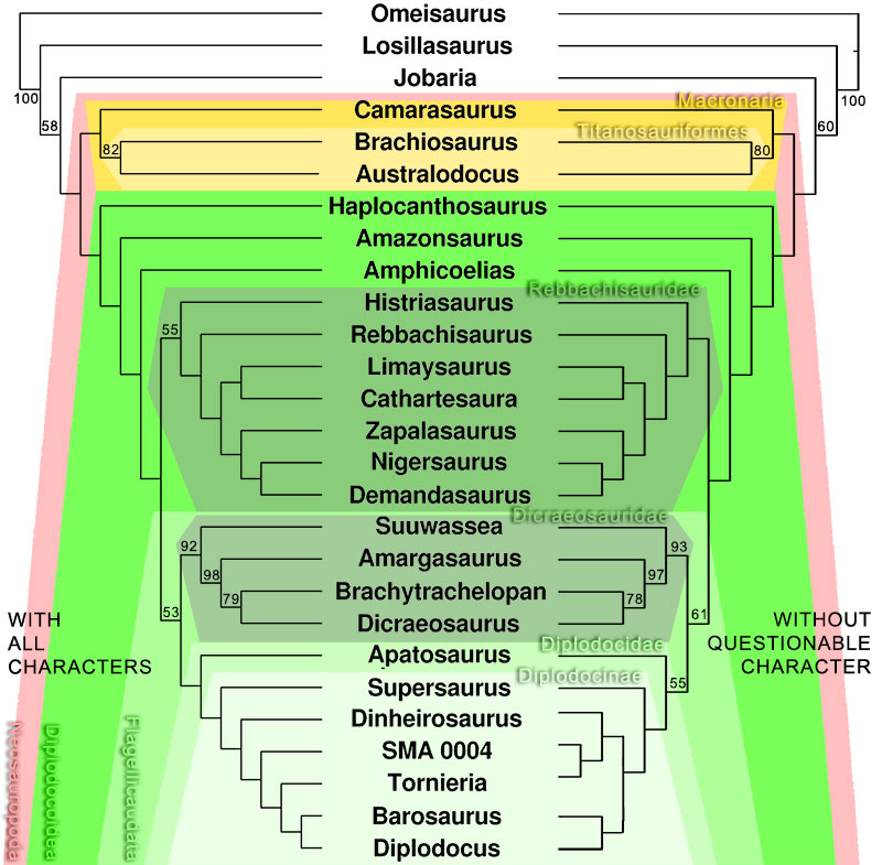
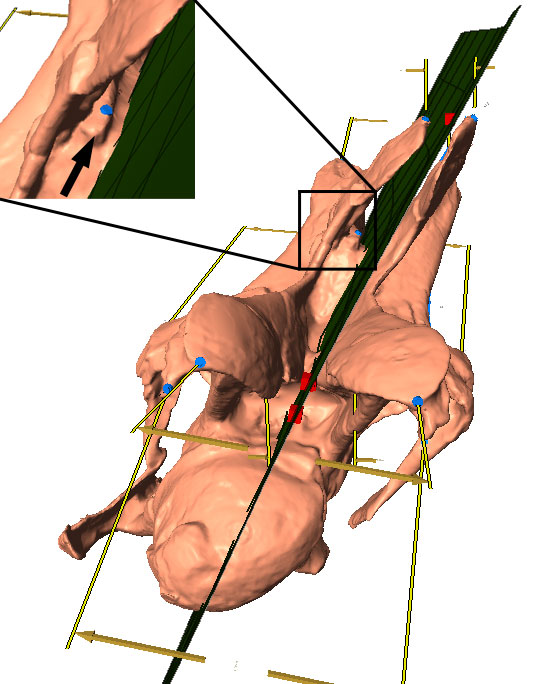
FIGURE 15. Calculated midsagittal plane on original model of CV 13 in oblique anterodorsal view. The used symmetrical pairs of landmarks are indicated in yellow and blue, the midsagittal plane in green. Note the medial tuberosity (arrow in close-up), which is supposed to lie on the midsagittal plane, but the methods used herein do not allow to include single points.