FIGURE 1. Hardware setup for biplanar X-ray analysis of footprint formation and its virtual counterpart. 1.1, experimental configuration for the repeated plunge trials. X-rays emitted from each source are captured by the image intensifier and recorded by video camera. The second image intensifier is largely hidden by the scissor lift. The rig has been simplified to show the cast foot model more clearly. 1.2, 3-D scene of key elements in Maya software (click here to view ANIMATION for 1.2). Each X-ray source is represented by a calibrated virtual camera, which views undistorted video from the correct perspective. Digital models are registered to reconstruct 3-D indenter and sediment marker motion within the volume of X-ray intersection.
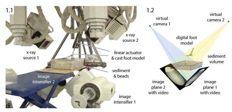
FIGURE 2. External and internal imaging of indenter and sediment motion. 2.1, a repeatable plunge sequence showing the cast foot model entering the soft substrate (click here to view VIDEO for 2.1). Several 2 mm lead beads are visible on the surface. 2.2, undistorted X-ray image as viewed through camera 2 (click here to view VIDEO for 2.2). Lead beads appear as black dots. 2.3, rotoscoped models foot cast (green), surface (red), sub-surface (aqua), and sub-tray (magenta) beads (click here to view ANIMATION for 2.3). Only a small fraction of the analyzed beads is visible externally in 1.1. Digit III is ~9 cm in length.
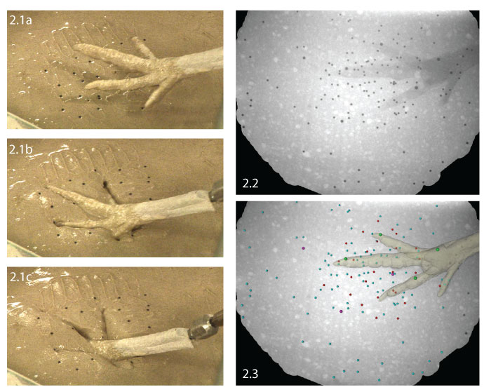
FIGURE 3. Estimate of precision based on the variability in six measured distances between the four beads embedded in the cast foot model. 3.1, within each trial, the standard deviation in inter-bead distance was less than 0.2 mm (mean 0.11 mm). 3.2, absolute deviation of average inter-bead distance from each trial was within 0.12 mm of the group mean.
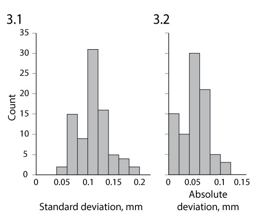
FIGURE 4. Position of 810 beads and the foot cast model compiled from 14 repeatable plunge trials (click here to view ANIMATION for 4). Axes are 1 cm in length.
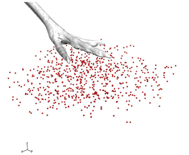
FIGURE 5. Summary of 810 bead paths compiled from 14 repeatable plunge trials. 5.1, perspective view (click here to view ANIMATION for 5.1). 5.2, dorsal view. 5.3, lateral view. 5.4, posterior view. Starting above the substrate (opaque model), the foot cast penetrated down and forward at 39° before stopping (transparent model) 4.5 cm below the original surface. Bead displacements dropped off rapidly with distance from the indenter. The foot drove nearby beads downward and forward, frequently along curving paths. Beads in front of the foot moved forward, outward, and upward. Axes are 1 cm in length.
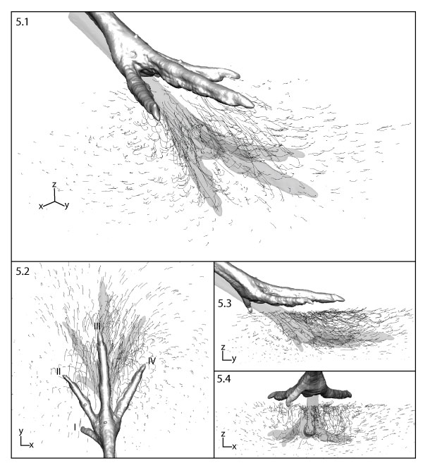
FIGURE 6. Bead motion during descent of the three main toes from the surface (opaque model) through the top 1 cm of sediment (transparent model) in lateral view. 6.1, a bead path visualization showing a dramatic dropoff in movement with starting depth. Axes are 1 cm in length. 6.2, plot of vertical bead displacement relative to starting depth. The foot model penetrated 1 cm (arrow); only a few beads near the surface descended as far. The indenter's influence decayed rapidly with starting depth. 6.3, beads in their starting position colored by 2 mm increments of downward displacement. Beads with a net upward motion are not shown.
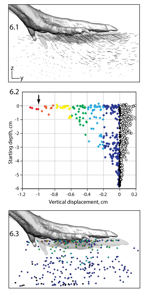
FIGURE 7. Detailed trajectories of seven beads affected by digit III. In world space, the descending toe drives the sediment markers down. 7.1, anterior view (click here to view ANIMATION for 7.1). 7.2, perspective view (click here to view ANIMATION for 7.2). All but the deepest bead diverge around the toe and then converge into a collapsed slit above. In the model's reference frame, sediment markers flow up toward, around, and over the stationary digit. 7.3, anterior view (click here to view ANIMATION for 7.3). 7.4, perspective view (click here to view ANIMATION for 7.4). Axes are 5 mm in length.
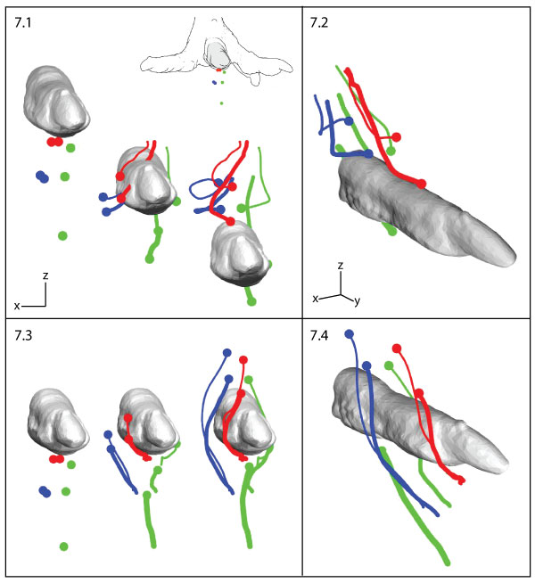
FIGURE 8. A full motion sequence of the turkey foot simulating penetration (8a-8b), mid-stance (8b-8c), withdrawal (8c-8d), and collapse (8d-8e) to create a deep track (click here to view VIDEO for 8). Digit III is ~9 cm in length.

FIGURE 9. Rotoscoped beads of a full motion trial as seen through camera 1 (click here to view ANIMATION for 9). Green beads are embedded in the foot, whereas red beads are in and on the substrate. The path of one bead is traced in red.
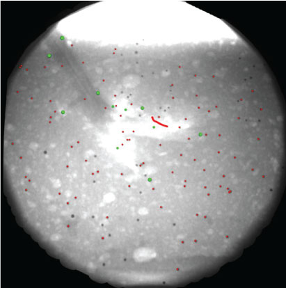
FIGURE 10. Reconstructed foot motion and bead paths from a full motion trial in lateral view (click here to view ANIMATION for 10). Beads embedded in the turkey foot are linked by rigid segments to represent the four digits (I-IV), tarsometatarsus (t), and spur (s). The path of one bead (red) is highlighted. Axes are 2 cm in length.
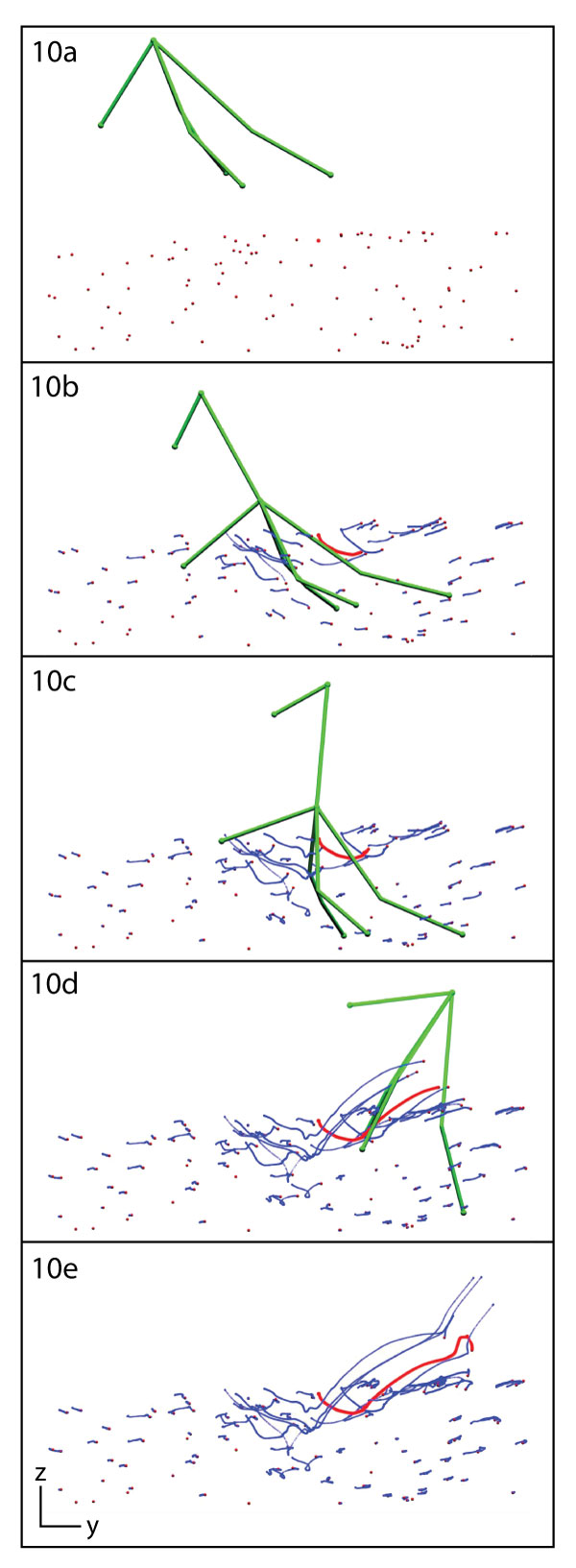
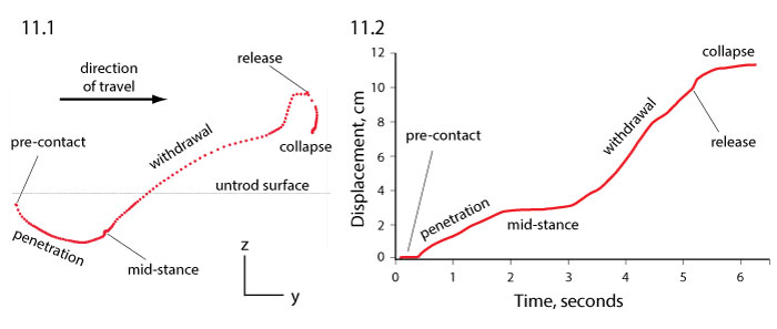
FIGURE 11. Motion of the bead highlighted in Figure 9 and Figure 10. 11.1, lateral view of the bead's trajectory (one point per frame) relative to the undisturbed sediment surface. Major events and the penetration, mid-stance, withdrawal, and collapse phases are designated. Axes are 1 cm in length. 11.2, cumulative displacement versus time graph. Phases of the tracking event are distinguished by changes in velocity (slope).