

 Quasi-homothetic transformation for comparing the mechanical performance of planar models in biological research
Article number: 16.3.6T
https://doi.org/10.26879/365
Copyright Palaeontological Association, November 2013
Author biographies
Plain-language and multi-lingual abstracts
PDF version
Submission: 6 November 2012. Acceptance: 11 October 2013
{flike id=468}
ABSTRACT
The potential of Finite Element Analysis (FEA) as an analytical technique in biological research has been widely highlighted in recent years. In spite of its great power, only in the best of circumstances one can compare the behaviour of models that differ in size and shape. Here, a new and easy procedure to scale FE models of plane elasticity is presented for several species of extant bovids that significantly differ in size and morphology. The method is based on the modification of the values of the forces applied by taking into account the particularities of the elasticity plane models (plane strain and plane stress equations) using quasi-homothetic transformations. This approach is shown to be extremely useful when exploring the effect of the shape in front of the strength and the stiffness of vertebrate bone structures. Thus, the quasi-homothetic concept is a new and interesting proposal to be used in plane elasticity models of biological, and specifically of vertebrate, structures which can be modelled as two-dimensional finite element models.
Jordi Marcé-Nogué. Departament de Resistència de Materials i Estructures a l'Enginyeria, Universitat Politècnica de Catalunya, 08222, Terrassa, Spain; jordi.marce@upc.edu
Daniel DeMiguel. Institut Català de Paleontologia Miquel Crusafont, Edifici ICP, Campus de la UAB s/n, 08193, Cerdanyola del Vallès, Spain; daniel.demiguel@icp.cat
Josep Fortuny. Institut Català de Paleontologia Miquel Crusafont, Edifici ICP, Campus de la UAB s/n, 08193, Cerdanyola del Vallès, Spain; josep.fortuny@icp.cat
Soledad de Esteban-Trivigno. Transmitting Science, Gardenia 2, Piera, 08784, Spain; Institut Català de Paleontologia Miquel Crusafont, Edifici ICP, Campus de la UAB s/n, 08193, Cerdanyola del Vallès, Spain; soledad.esteban@transmittingscience.org
Lluís Gil. Departament de Resistència de Materials i Estructures a l'Enginyeria, Universitat Politècnica de Catalunya, 08222, Terrassa, Spain; lluis.gil@upc.edu
Keywords: FEA; homothetic transformation; plane elasticity; size; morphology; continuum mechanics
Final Citation: Marcé-Nogué, Jordi, DeMiguel, Daniel, Fortuny, Josep, de Esteban-Trivigno, Soledad, and Gil, Lluís. 2013. Quasi-homothetic transformation for comparing the mechanical performance of planar models in biological research, Palaeontologia Electronica Vol. 16, Issue 3; 6T; 15p. https://doi.org/10.26879/365
palaeo-electronica.org/content/2013/468-quasihomothetic-transformation
INTRODUCTION
Finite Element Analysis (FEA) is a widely known computer simulation technique for analysing the response of materials to specific loading conditions (Zienkiewicz 1971). Although commonplace in engineering and biomedicine for more than 30 years, only recently it has been applied in biological research to address questions about biomechanics and evolution of living and extinct vertebrates (Rayfield et al., 2001; Rayfield, 2004, 2007; Dumont et al., 2005; Richmond et al., 2005; Ross, 2005; DeMiguel et al., 2006; Kupczik et al., 2007; Wroe et al., 2007; Pierce et al., 2008; Fortuny et al., 2011)
To date, most of the FE studies have focused specifically on comparing 3D models of different species (Macho et al., 2005; Dumont et al., 2005, 2011; McHenry et al., 2006 ; Wroe et al., 2007; Slater and Van Valkenburgh, 2009; Slater et al., 2010, 2009; Strait et al., 2010; Tseng et al., 2011; Rivera and Stayton, 2011; Santana and Dumont, 2011; Chamoli and Wroe, 2011; Van Der Meijden et al., 2012; Oldfield et al., 2012), and the interest in comparative analysis is increasing with the common usage of FEA in biomechanics. The main interest of these studies is to model the shape of a specific anatomical structure in order to infer its mechanical behaviour and function and relate it to different ecological adaptations (e.g., feeding, flight, swimming, etc.).
It should be noted, however, that there has been a trend towards decreasing use of plane models–probably because advances in computer technology have made the use of more demanding 3D models easier– and only a few of the biological FE models described in the literature assume the hypothesis that the studied structure can be analysed in 2D (Rayfield, 2004, 2005; Pierce et al., 2008, 2009; Fletcher et al., 2010), although representing a powerful tool in scientific developments (Anderson et al., 2012 ; Hutchinson, 2012).
Plane models can certainly be used as a first and easy approximation to the study of the behaviour of the vertebrate bone structures since they 1) allow researchers to speed up the reconstruction process (models can be effectively created by digitizing photographs or other electronic images, while no CT or 3D scanners are needed), 2) significantly reduce the computational analysis time, and 3) allow to design a strategy to deal with subsequent and more detailed 3D models (Rayfield, 2004). The plane procedure is particularly suitable for comparing models of different species when the structure and the loads are located in a plane whereas geometry, constraints and material properties are uniform in the out-of-plane direction. In that case, the comparative sample can be enlarged because the duty of creating and analysing the models could be highly reduced with it (Pierce et al., 2008; Fletcher et al., 2010; Fortuny et al., 2011, 2012).
From a biological point of view, there are many situations where it is important to consider shape and size independently. Scaling (that is, the analysis of the individuals as making them of equivalent size) provides a useful tool for exploring differences in shape among individuals and species. In comparative FEA analysis is important to apply equal forces to the model for making results from different specimens comparable. However, since specimens in biology usually have different sizes, the fact of using the same value of force for all of them would be incorrect, and a way to scale specimens (and use equivalent forces) is needed (Marcé-Nogué et al., 2012).
Several approaches have been suggested to standardize for size. Some recent works have discussed how to scale the models to the same size in 3D to study the stress patterns or the strain energy (see Dumont et al., 2009 for a discussion), thus proposing that size could be removed either by modifying the dimensions of the model or the values of the forces applied. On the other hand, other relevant studies have been carried out on plane models to remove the size effect, but are based on complex landmark-based and geometric morphometric analyses (Pierce et al., 2008, 2009). Despite this complexity, such procedure significantly simplifies the outline morphology for FE analyses andcould result in more inaccurate models.
Taking all these facts into consideration, and because FEA continues to rise among biologists, the purpose of this study is to create and discuss a new and easy procedure to scale the specimens in plane models, which is based on the modification of the values of the forces applied by taking into account the particularities of the elasticity plane models in FEA (plane strain and plane stress equations). The accuracy of our model was verified, and the approach is shown to be extremely useful when comparing the strength and the stiffness of different species' vertebrate bone structures.
MATERIAL AND METHODS
Quasi-homothetic Equations Addressed to Remove Size in Plane Elasticity
In continuum mechanics, plane elasticity refers to the study of particular solutions of the general elastic problem, which are reducible to elastic 2D problems (Mase, G.E. and Mase, G.T., 1999). This simplification is possible only in bodies that are geometrically mechanical prisms (that is, an area with a constant thickness) and depend on the type of forces or stresses to which the prism is submitted. These loads must lie in a plane, and material properties and constraints must be uniform out-of-plane (Mase, G.E. and Mase, G.T., 1999).
In practical applications, two different types of states of plane elasticity are differentiated. First, a state of plane stress exists when one of the three principal stresses is zero. This usually occurs in structural elements where one dimension is very small compared to the other two, and the stresses are negligible with respect to the smaller dimension. Second, a state of plane strain exists when one dimension is very large compared to the others, the principal strain in the direction of the longest dimension is constrained and can be assumed as zero. It happens in prismatic structures where the length of the structure is much greater than the other two dimensions.
In plane stress, the thickness of the model must be defined outside of the mathematical procedure instead of plane strain where the thickness is always considered as unitary. In both cases the relationship between stress and strain is assumed to be linear according to the behaviour of the elastic materials that follows the Hooke's Law as a constitutive equation. The linearity of the constitutive behaviour of bone tissue in vertebrate structures is a known assumption to obtain accurate results (Doblare, 2004).
Dumont and colleagues (Dumont et al., 2009) proposed two options for the scaling of 3D models: Option A) models should be scaled to the same surface area or volume and the same total load should be applied to each one (Slater and Van Valkenburgh, 2009; Slater et al., 2009; Rivera and Stayton, 2011; Santana and Dumont, 2011; Dumont et al., 2011; Chamoli and Wroe, 2011; Oldfield et al., 2012) . Option B) to remove the differences in size by scaling the applied loads to maintain a constant value of force per unit surface area (Jasinoski et al., 2010). According to this last recommendation, our aim is to define the proportion between the forces in one model in relation with other model, in order to maintain the stress state or the displacements proportionally constant when the size of the structure is different.
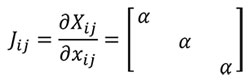
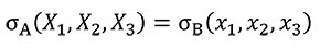
A transformation between one sample and another can be written using the function xj= Ø (Xi) as a mapping between geometries (Malvern, 1969), where Xi=1..3 is the reference sample, xj=1..3 the other sample and Ø the mathematical transformation. Herein the relationship between samples can be written as dXi = Jijdxj and dxj = J-1ijdXi where Jij is the Jacobian. In a homothetic transformation Jij is a diagonal matrix which describes a linear transformation with J11=J22=J33(Equation 1) to maintain the same proportionality in the three directions of the space.
 (1)
(1)
Where α is the linear scaling constant in a homothetic transformation. Using Equation (1), Table 1 shows the mathematical relationship in a homothetic transformation (Figure 1) for relationship between lineal entities (segments) and quadratic entities (surface).
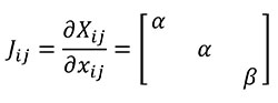
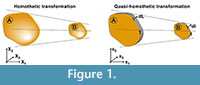 We define herein a new transformation procedure called "quasi-homothetic transformation" (Figure 1) due to the particularity of plane elasticity. In a quasi-homothetic transformation Jij is a diagonal matrix which describes a linear transformation with J11 = J22 ≠ J33 (2), maintain the proportionality in two directions of the space and a different proportion in the third. In this transformation the thickness is assumed to be as the third direction and considered as a constant dimension along the same sample because the thickness of the sample must be defined outside the mathematical equations. This is done assuming α as the linear scaling constant for an in-plane homothetic transformation and adding β as the linear scaling constant of the thickness as shown in Equation (2)
 (2)
(2)
Using Equation (2), Table 1 also shows the mathematical relationship in a quasi-homothetic transformation between lineal entities (segments) and quadratic entities (surface) including the thickness in the formulation. The lineal entities are subdivided between transformations along the thickness of the plane models and along a segment l defined in the plane of the plane surface.
Constant Stress Distribution in a Quasi-homothetic Transformation
In order to analyse the influence of the shape in front of the strength, Equation (3) needs to be fulfilled to hold the same stress distribution between models when a quasi-homothetic transformation is done between two different plane models A and B.
 (3)
(3)
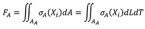
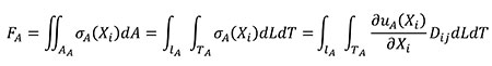
The relationship between the forces applied in models A and B is obtained starting from Equation (4) where, by definition, the resultant of the stress distribution in the area where they are located is a resulting force. The equation is written in terms of the coordinates of the A state considering that dA can be written as dLdT.
 (4)
(4)
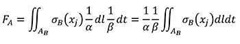
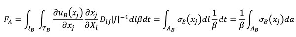
Using the relationships of the Table 1 for quasi-homothetic transformations, FA can be rewritten in Equation (5) changing variables to transform the expression in terms of the coordinates of the B state and adding the fulfilment of Equation (3).
 (5)
(5)
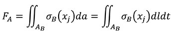
And according that, by definition, FB in terms of the coordinates of the B state is Equation (6)
 (6)
(6)
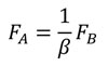
Finally the relationship between FA and FB can be written as Equation (7).
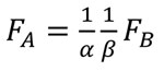 (7)
(7)
Constant Displacements in a Quasi-homothetic Transformation
In order to analyse the influence of the shape in front of the stiffness, Equation (8) needs to be fulfilled to hold the same displacement distribution between models when a quasi-homothetic transformation is done between two different plane models A and B.
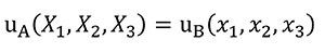 (8)
(8)
In this case Hooke's Law (Mase, G.E. and Mase, G.T. 1999) is used to relate stress and strains of the states A and B (Equations 9 and 10).
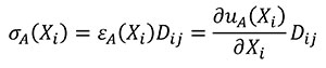 (9)
(9)
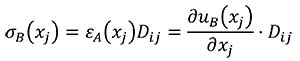 (10)
(10)
Where D is the elastic tensor of the constitutive law which relates stresses and strains. D contains the elastic constants of the material. The relationship between the forces applied in models A and B is obtained starting from Equation (11) where, by definition, the resultant of the stress distribution in the area where they are located is a resulting force. The equation is written in terms of the coordinates of the A state considering that dA can be written as dLdT and adding the relationship between stress and strains described in Equation (9).
 (11)
(11)
For the change of variables of derivatives from coordinates of the A state to coordinates of the B state, the chain rule is used as shown in Equation (12).
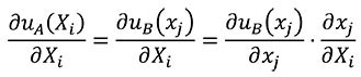 (12)
(12)
Using the relationships of the Table 1 for quasi-homothetic transformations, FA can be rewritten in Equation (13) by changing the variables to transform the expression in terms of the coordinates of the B state and adding the fulfilment of Equation (8)
 (13)
(13)
And according that, by definition, FB in terms of the coordinates of the B state is shown in Equation (6), finally the relationship between FA and FB can be written as Equation (14).
 (14)
(14)
Data Collection and Finite Element Analysis (FEA)
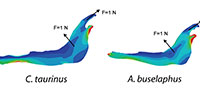
We used planar 2D models of different bovid jaw species in order to evaluate the influence of shape of the models while controlling size parameters. We selected the following four species of extant bovids (Mammalia, Ruminantia) that significantly differ in size and morphology: Connochaetes taurinus, Alcelaphus buselaphus, Hippotragus niger and Kobus vardoni. The specimens analysed are housed at the American Museum of Natural History (AMNH, New York) and the Museum für Naturkunde (MfN, Berlin). According to the assumption of usual simplifications of 2D analysis, the thickness in each model is considered constant, and the bovine haversian bone is considered as a lineal, elastic and homogeneous material (E [Young´s modulus]=10 GPa and v [Poisson ratio]=0.4)(Reilly and Burstein, 1975).
The reconstruction of the 2D FE models starts from photographs of the jaw in lateral view, which were digitized and treated to be suitable in FEA according to the steps defined in previous works (Fortuny et al., 2011). The analysis was developed using ANSYS FEA Package v.13 for Windows 7 (32-bit system) in order to obtain the stresses and deformations of the 2D models.
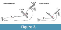 For each model, a starting mesh was automatically generated by the FEA Package and convergence tools were used to refine the mesh in particular points of interest (as described in Fortuny et al., 2011) to ensure the recorded value. As points of interest, two points P (most mesial point of the first premolar at the alveolus), and Q (most distal point of the third molar at the alveolus) were placed in the jaws to record the values of Von Mises stress and displacements (Figure 2).
There is a wide spectrum of possibilities of results to display in FEA (different types of stresses, strains, displacements, etc.), but the most usual in the study of vertebrate structures is the Von Mises stress (Doblare, 2004). This is an isotropic criterion traditionally used to predict the yielding of ductile materials such as metals, but according to Doblare et al. (Doblare, 2004) when isotropic material properties are used in cortical bone, the Von Mises criterion may be the most accurate for predicting fracture location. The displacements are also a common and useful result to display in FEA when biological systems are analysed.
To accomplish our goals, we applied the scaling in two different ways. A first case study is proposed in order to demonstrate that, for the same 2D model, if a change of size is applied creating a scaled model, there is a relationship between the forces that allows keeping both stress state and displacements constant. In this case, the jaw of Connochaetes taurinus is analysed.
Once the validity and accuracy of the equations is verified, a second case study is proposed with the aim of demonstrating how it should be used in comparative analysis, by applying the correction to different bovid species in order to remove the differences in size. Firstly, the four jaws are analysed using the same value of unitary force (1 N) without creating a methodology that enables the comparison between them. Secondly, the mathematical relationships between forces are defined for plane stress and plane strain to hold the same distribution for stresses or displacements in different models in order to compare the four jaws in a quasi-homothetic transformation.
It must be noted that the strain state is not considered because the lineal relationship defined for the material properties assures that when the same stress distribution is held between models the strain state also will be constant. This implies that the relationships defined for conserving the state of stress are the same as those for conserving the state of strain.
RESULTS
Case Study 1: Connochaetes taurinus
A 2D model of the Connochaetes taurinus jaw is used with the purpose to compare the results obtained by FEA on the stress state and the displacements. A first model (to be used as a reference) was constrained at both the condyle and the anterior part of the diastema and arbitrary muscle forces with a value of 1 N were applied both in the masseter and in the temporalis in directions appropriate for the relative direction of force during chewing (see Figure 2).
The following models correspond to the same specimen of Connochaetes taurinus scaled to a different size, and adequate forces have been applied afterwards to maintain the stress state or the displacement field constant. This fact is due to the linear relationship between the stress and the strains, which are established by Hooke's law. For this reason, an adequate force to maintain the stress state constant and another one to maintain the displacement constant are found. The relationship is established for plane stress and plane strain.
We obtained the relationship between the reference model (model A) and any other scaled model (model B) in Table 2 from the above mentioned Equations (2) and (5). AA is the area of the reference model, AB the area of the scaled model, tA is the thickness of the reference model and tB the thickness of the scaled model. Following Equation (1), the results are: the constant 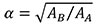 and the constant β = tB/tA. In plane strain the relationship is according to the own definition of plane strain where the thickness of a plane strain model is unitary for both models of reference.
 The equations shown in Table 2 were applied to the four random scaled models of Connochaetes taurinus. The thickness and the surface of each model are shown in Table 3. The force applied in each scaled model according to the equations of plane stress and plane strain using these values of area and thickness are drawn in Figure 3.
As can be noted in Figure 3, the coloured distribution of the Von Mises stress is shown for scaled models where the same stress distribution is held constant, and the displacement coloured distribution is shown for the scaled models where the displacements are also constant (see Table S1 for numerical results in points P and Q according to the points in Figure 2).
Case Study 2: Comparison of Four Different Models of Bovine Jaws
Four 2D models of bovine jaws (Connochaetes taurinus, Alcelaphus buselaphus, Hippotragus niger and Kobus vardoni) were used with the objective of comparing the results obtained by FEA on the stress state and the displacements. The models show the previously mentioned boundary conditions and loading. In this second case, the models have both different area and thickness, as shown in Table 4.
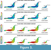
 Firstly, the same unitary force (1N) is applied in each model (Figure 4) without the application of the scaled values of forces. This case study compares the models without considering the quasi-homothetic transformation. The distribution obtained for Von Mises stresses and the displacement field can be observed in Figure 4 (see Table S2 for numerical results in points P and Q according to the points in Figure 2).
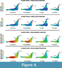
Secondly, we obtain the adequate force to maintain the stress state constant and the adequate force to maintain the displacement constant as a quasi-homothetic transformation. The relationship is established for plane stress and plane strain in order to supress the differences in size and be able to study and compare the effect of the shape between different jaws (equations in Table 2). The thickness and the surface of each model are shown in Table 4. The force applied in each state according to the equations in Table 2 is shown in Figure 5. We used the real dimension of Connochaetes taurinus as a reference to scale the forces in the other jaws.
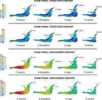 As observed from Figure 5, the coloured distribution of the Von Mises stress of the jaws is shown for the models where the same stress distribution is held between them, and the displacement coloured distributions are shown for the models where the displacements are constant between models (see Table S3 for numerical results in points P and Q according to the points in Figure 2).
DISCUSSION
As observed in case 1, the results for the four scaled models have the same displacement and stress values when the forces are scaled to hold the same displacement and stress distribution, respectively. This fact points to the conclusion that the methodology to scale the forces presented herein is proved as a good way to remove the differences in size in order to compare 2D models in plane stress and strain when the same stress and displacement distribution is held between them.
Small differences in the obtained Von Mises stresses of about 1% can be observed. For example, Von Mises stress is recorded for 0.07334MPa in point P in the reference state and 0.072596 MPa for the scaled model 4. Another example is when the same displacement distribution is held in a plane strain analysis, the difference between the values for the reference model with respect to the model 2 are also about 1% (e.g., displacement is recorded as 0.0043134 mm in point P in the reference state and 0.004359 mm for the scaled model 2). Nonetheless, all these small differences can be omitted in the evaluation of the results, considering the results obtained as exactly the same for each scaled model with respect to the reference model, because the change of the size of the model implies a change in the mesh density. Studies on FEA have shown that small changes in the mesh of an FE model can produce small differences in the numerical results, because the results depend in part on the characteristics of the mesh (Bright and Rayfield, 2011).
In case 2, where all the four models belong to different species, it is noted that an obvious stress state and displacement field different for each jaw is obtained. This difference occurs despite applying a unitary force in all the models or the mathematical relationships between the reference Connochaetes taurinus model and the other three (Alcelaphus buselaphus, Hippotragus niger and Kobus vardoni) models. Further, the values recorded in the points P and Q (see Tables S2 and S3) are logically different because of differences in jaw shape. The differences between the results obtained when a unitary force is applied in all the models and the results obtained when the force is scaled using the quasi-homothetic formulation indicates that the value of the force should be taken into account because it influences the final result. For the first procedure, we used the same force value and obtained results that cannot be compared because the four jaws exhibit different values of area and thickness. For the second procedure, and according to the relationship between forces when a quasi-homothetic transformation is applied, we obtained a Von Mises stress distribution and displacement fields that can be compared between the specimens. Here, the differences in size were removed and only taken into account the effects of the shape of the different jaws using the new equations proposed.
Our equations reach the same objective of the procedure designed by Pierce and collaborators to obtain final FEA models of several vertebrate structures removing the size effects (Pierce et al., 2008, 2009), although with the advantage of creating the geometry of the FEA model directly from the CAE file. This fact is important, since the creation of FE models from each landmark configuration may lead to problematic results with artificial noise due to the simplification of the shape during the process. It is widely known that the artificial noise in the stress maps is due to the selection of fixed points as boundary conditions, the application of punctual forces, and the presence of idealized geometries as perfect squares (Marcé-Nogué et al., 2011).For a comparative analysis, researchers need to be very cautiousnot to choose values of stress in points close to the artificial noise.
Finally, and considering stiffness as the rigidity of the model (the extent to which it resists deformation in response to an applied force), the stiffness of the model is here evaluated with the displacements field instead of the strain energy. For comparing stiffness, the models can also be compared with the value of the strain energy (Slater et al., 2010; Strait et al., 2010; Tseng et al., 2011; Dumont et al., 2011; Van Der Meijden et al., 2012) because models that are stiffer spend less energy to deform. Dumont et al. (Dumont et al., 2009) have also correlated the relationship between surface and forces of different 3D models in order to compare them using the strain energy. The advantage of using the displacements is that we have information of the behaviour in the whole model but when obtaining the strain energy we only have one value for the model. However, a mathematical relationship for the quasi-homothetic transformation could be easily obtained following the same procedure of Equations (4) and (7).
It should be noted that adjusting the forces to the size of each structure makes it possible to have a comparative analysis, it is not correcting for allometric effects. If allometric relationships exist, part of the differences in shape between animals of different sizes will be due to simple geometric constraints (Schmidt-Nielsen, 1984; West et al., 1997). When applying the procedure described here, allometry could be present despite the scaling. In a FEA context, correcting by size effects has been applied in a few cases after getting the results (McHenry et al., 2007; Chamoli and Wroe, 2011), and indeed in some cases before generating the models, on the same structure (Pierce et al., 2008, 2009).
However, the fact of whether to correct or not by allometry will depend on the biological questions addressed in each case. Because so many ecological and physiological variables correlate with size, when animals grow larger they alsochange their functions too. For example, within ruminants there is a relationship between diet and size of the animal (Mysterud et al., 2001). If a study would be directed to model the behaviour of the jaw in relation with the diet, removing the allometric effects will remove part of the differences in shape related to function, as size and function are intertangled.
Biology structures are integrated into complex systems, being its shape a compromise between its function/s and many other factors (functions of related structures, phylogenetic and developmental constrains, etc.). Therefore allometry is one of many other biological effects that researchers have to bear in mind when interpreting the results of FEA analysis in a biological context. More discussion is needed regarding this analysis and how to integrate the results into the complexity of a living being. What is clear is that if we aim to compare the biomechanical response of a structure between different species (i.e., in a comparative framework) scaling is needed to make forces equivalent. In the case of planar structures, to apply quasi-homothetic transformation has been shown an adequate and indispensable procedure.
CONCLUSIONS
In this paper, we present a new method and equations in Finite Element Analysis for controlling the differences in size in plane elasticity and compare only the effects of shape on structural strength, which is a fundamental, yet inconvenient, requirement when comparing plane vertebrate structures.
Importantly, the method is an easy procedure that does not involve either the use of new software or changes in the classical methodology of FEA. It can be easily applied by only modifying the values of the forces applied in the model to an adequate value calculated using the equations presented here in order to study the stress patterns or the displacement fields as indicators of strength and stiffness.
Our model highlights the importance of the quasi-homothetic concept to be used in plane elasticity models of biological structures which can be modelled as two-dimensional finite element models. This concept could be therefore used in future works of biological models by adapting its formulation to the physical problem desired.
ACKNOWLEDGEMENTS
This research has been supported by projects CGL2010-19116, CGL2010-21672 and CGL2011-30069-C02-01 of the Spanish Ministerio de Economía y Competitividad, and contracts JCI-2011-11697 to DDM and Synthesis project DE-TAF 1779 2 to SdET. The quality of this manuscript has been improved thanks to the comments of the editor and two anonymous reviewers.
REFERENCES
Anderson, P.S.L., Bright, J. a, Gill, P.G., Palmer, C., and Rayfield, E.J. 2012. Models in palaeontological functional analysis. Biology letters, 8:119–22. doi:10.1098/rsbl.2011.0674.
Bright, J. a and Rayfield, E.J. 2011. The response of cranial biomechanical finite element models to variations in mesh density. Anatomical record (Hoboken, N.J.?: 2007) 294:610–20. doi:10.1002/ar.21358.
Chamoli, U. and Wroe, S. 2011. Allometry in the distribution of material properties and geometry of the felid skull: why larger species may need to change and how they may achieve it. Journal of Theoretical Biology, 283:217–226. doi:10.1016/j.jtbi.2011.05.020.
DeMiguel, D., Cegoñino, J., Azanza, B., Ruiz, I., and Morales, J. 2006. Application of the 3D finite element analysis in the biomechanical study of the mammalian teeth. Preliminary analysis in Procervulus ginsburgi (Cervidae, Artiodactyla). Estudios Geológicos, 62:115–121,
Doblare, M. 2004. Modelling bone tissue fracture and healing: a review. Engineering Fracture Mechanics, 71:1809–1840.
doi:10.1016/j.engfracmech.2003.08.003.
Dumont, E.R., Grosse, I.R., and Slater, G.J. 2009. Requirements for comparing the performance of finite element models of biological structures. Journal of Theoretical Biology 256:96–103. doi:10.1016/j.jtbi.2008.08.017.
Dumont, E.R., Piccirillo, J., and Grosse, I.R. 2005. Finite-element analysis of biting behavior and bone stress in the facial skeletons of bats. The anatomical record. Part A, Discoveries in molecular, cellular, and evolutionary biology, 283:319–30. doi:10.1002/ar.a.20165.
Dumont, E.R., Davis, J.L., Grosse, I.R., and Burrows, A.M. 2011. Finite element analysis of performance in the skulls of marmosets and tamarins. Journal of Anatomy, 218:151–62.
doi:10.1111/j.1469-7580.2010.01247.x.
Fletcher, T.M., Janis, C.M., and Rayfield, E.J. 2010. Finite element analysis of ungulate jaws: Can mode of digestive physiology be determined? Palaeontologica Electronia, Vol. 10, Issue 3, 21A; 15p;
palaeo-electronica.org/2010_3/234/index.html.
Fortuny, J., Marcé-Nogué, J., Gil, Lluis, and Galobart, A. 2012. Skull mechanics and the evolutionary patterns of the otic notch closure in capitosaurs (Amphibia: Temnospondyli). Anatomical Record 295:1134–46. doi:10.1002/ar.22486.
Fortuny, J., Marcé-Nogué, J., De Esteban-Trivigno, S., Gil, Lluís, and Galobart, Á. 2011. Temnospondyli bite club: ecomorphological patterns of the most diverse group of early tetrapods. Journal of Evolutionary Biology 24:2040–54.
doi:10.1111/j.1420-9101.2011.02338.x.
Hutchinson, J.R. 2012. On the inference of function from structure using biomechanical modelling and simulation of extinct organisms. Biology letters, 8:115–8. doi:10.1098/rsbl.2011.0399.
Jasinoski, S.C., Rayfield, E.J., and Chinsamy, A. 2010. Functional implications of dicynodont cranial suture morphology. Journal of Morphology 271:705–28. doi:10.1002/jmor.10828.
Kupczik, K., Dobson, C. a, Fagan, M.J., Crompton, R.H., Oxnard, C.E., and O'Higgins, P. 2007. Assessing mechanical function of the zygomatic region in macaques: validation and sensitivity testing of finite element models. Journal of Anatomy 210:41–53. doi:10.1111/j.1469-7580.2006.00662.x.
Macho, G.A., Shimizu, D., Jiang, Y., and Spears, I.R. 2005. Australopithecus anamensis: a finite-element approach to studying the functional adaptations of extinct hominins. The Anatomical Record, 283:310–318.
Malvern, L.E. 1969. Introduction to the Mechanics of a Continuous Medium. Prentice-Hall.
Marcé-Nogué, J., Fortuny, J., Gil, Lluís, and Galobart, Á. 2011. Using Reverse Engineering to Reconstruct Tetrapod Skulls and Analyse its Feeding Behaviour Proceedings of the Thirteenth International Conference on Civil, Structural and Environmental Engineering Computing.
Marcé-Nogué, J., DeMiguel, D., Fortuny, J., De Esteban-Trivigno, S., and Gil, Lluís. 2012. New equations and methods for solving the size effects in the comparison of 2D Finite Element Analysis, 10th European Association of Vertebrate Palaeontologists Meeting.
Mase, G.E. and Mase, G.T. 1999. Continuum Mechanics for Engineers. CRC Press.
McHenry, C.R., Clausen, P.D., Daniel, W.J.T., Meers, M.B., and Pendharkar, A. 2006. Biomechanics of the rostrum in crocodilians: a comparative analysis using finite-element modeling. The anatomical record. Part A, Discoveries in molecular, cellular, and evolutionary biology, 288:827–49. doi:10.1002/ar.a.20360.
McHenry, C.R., Wroe, S., Clausen, P.D., Moreno, K., and Cunningham, E. 2007. Supermodeled sabercat, predatory behavior in Smilodon fatalis revealed by high-resolution 3D computer simulation. Proceedings of the National Academy of Sciences of the United States of America, 104:16010–5.
doi:10.1073/pnas.0706086104.
Mysterud, A., Pérez-Barbería, F.J., and Gordon, I.J. 2001. The effect of season, sex and feeding style on home range area versus body mass scaling in temperate ruminants. Oecologia, 127:30–39. doi:10.1007/s004420000562.
Oldfield, C.C., McHenry, C.R., Clausen, P.D., Chamoli, U., Parr, W.C.H., Stynder, D.D., and Wroe, S. 2012. Finite element analysis of ursid cranial mechanics and the prediction of feeding behaviour in the extinct giant Agriotherium africanum. (A. Kitchener, Ed.) Journal of Zoology, 286:171–171.
doi:10.1111/j.1469-7998.2011.00862.x.
Pierce, S.E., Angielczyk, K.D., and Rayfield, E.J. 2008. Patterns of morphospace occupation and mechanical performance in extant crocodilian skulls: a combined geometric morphometric and finite element modeling approach. Journal of Morphology, 269:840–64. doi:10.1002/jmor.10627.
Pierce, S.E., Angielczyk, K.D., and Rayfield, E.J. 2009. Shape and mechanics in thalattosuchian (Crocodylomorpha) skulls: implications for feeding behaviour and niche partitioning. Journal of Anatomy, 215:555–76. doi:10.1111/j.1469-7580.2009.01137.x.
Rayfield, E.J. 2004. Cranial mechanics and feeding in Tyrannosaurus rex. Proceedings. Biological sciences / The Royal Society 271:1451–9.
doi:10.1098/rspb.2004.2755.
Rayfield, E.J. 2005. Aspects of comparative cranial mechanics in the theropod dinosaurs Coelophysis, Allosaurus and Tyrannosaurus. Zoological Journal of the Linnean Society, 144:309–316.
doi:10.1111/j.1096-3642.2005.00176.x.
Rayfield, E.J. 2007. May. Finite Element Analysis and Understanding the Biomechanics and Evolution of Living and Fossil Organisms. Annual Review of Earth and Planetary Sciences, 35:541–576.
doi:10.1146/annurev.earth.35.031306.140104.
Rayfield, E.J., Norman, D.B., Horner, C.C., Horner, J.R., Smith, P.M., Thomason, J.J., and Upchurch, P. 2001. Cranial design and function in a large theropod dinosaur. Nature, 409:1033–7. doi:10.1038/35059070.
Reilly, D.T. and Burstein, A.H. 1975. The elastic and ultimate properties of compact bone tissue. Journal of Biomechanics, 8:393–405.
doi:10.1016/0021-9290(75)90075-5.
Richmond, B.G., Wright, B.W., Grosse, I.R., Dechow, P.C., Ross, C.F., Spencer, M. a, and Strait, D.S. 2005. Finite element analysis in functional morphology. The anatomical record. Part A, Discoveries in molecular, cellular, and evolutionary biology 283:259–74.
doi:10.1002/ar.a.20169.
Rivera, G. and Stayton, C.T. 2011. Finite element modeling of shell shape in the freshwater turtle Pseudemys concinna reveals a trade-off between mechanical strength and hydrodynamic efficiency. Journal of Morphology, 272:1192–1203.
doi:10.1002/jmor.10974.
Ross, C.F. 2005. Finite element analysis in vertebrate biomechanics. The anatomical record. Part A, Discoveries in molecular, cellular, and evolutionary biology, 283:253–8. doi:10.1002/ar.a.20177.
Santana, S.E. and Dumont, E.R. 2011. Do roost-excavating bats have stronger skulls? Biological Journal of the Linnean Society, 102:1–10. doi:10.1111/j.1095-8312.2010.01551.x.
Schmidt-Nielsen, K. 1984. Scaling, Why Is Animal Size So Important? Cambridge University Press.
Slater, G.J. and Van Valkenburgh, B. 2009. Allometry and performance: the evolution of skull form and function in felids. Journal of Evolutionary Biology, 22:2278–2287.
Slater, G.J., Dumont, E.R., and Van Valkenburgh, B. 2009. Implications of predatory specialization for cranial form and function in canids. Journal of Zoology, 278:181–188.
doi:10.1111/j.1469-7998.2009.00567.x.
Slater, G.J., Figueirido, B., Louis, L., Yang, P., and Van Valkenburgh, B. 2010. Biomechanical Consequences of Rapid Evolution in the Polar Bear Lineage. PLoS ONE 5:7.
Strait, D.S., Grosse, I.R., Dechow, P.C., Smith, A.L., Wang, Q., Weber, G.W., Neubauer, S., Slice, D.E., Chalk, J., Richmond, B.G., Lucas, P.W., Spencer, M.A., Schrein, C., Wright, B.W., Byron, C.D., and Ross, C.F. 2010. The structural rigidity of the cranium of Australopithecus africanus: implications for diet, dietary adaptations, and the allometry of feeding biomechanics. Anatomical record Hoboken NJ 2007, 293:583–593.
Tseng, Z.J., Mcnitt-Gray, J.L., Flashner, H., Wang, X., and Enciso, R. 2011. Model Sensitivity and Use of the Comparative Finite Element Method in Mammalian Jaw Mechanics: Mandible Performance in the Gray Wolf. PLoS ONE 6:12.
Van Der Meijden, A., Kleinteich, T. and Coelho, P. 2012. Packing a pinch: functional implications of chela shapes in scorpions using finite element analysis. Journal of Anatomy 220:423–434.
doi:10.1111/j.1469-7580.2012.01485.x.
West, G.B., Brown, J.H., and Enquist, B.J. 1997. A general model for the origin of allometric scaling laws in biology. Science, 276:122–126.
Wroe, S., Clausen, P.D., McHenry, C.R., Moreno, K., and Cunningham, E. 2007. Computer simulation of feeding behaviour in the thylacine and dingo as a novel test for convergence and niche overlap. Proceedings. Biological sciences / The Royal Society, 274:2819–28. doi:10.1098/rspb.2007.0906.
Zienkiewicz, O.C. 1971. The Finite Element Method in Engineering Science. Finite Element Methods In Engineering Science, 98–359. McGraw-Hill.
