FIGURE 1. Map modified from Mehlqvist et al. (2014) showing the location of the Ramsåsa area (1), and the Ramsåsa localities of Grönwall (1897) with an arrow indicating site E (2) adapted from Vergoossen (2004).
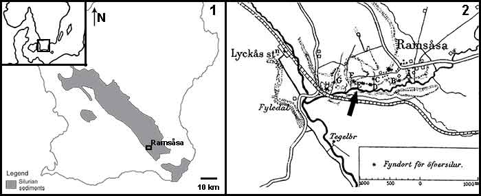
FIGURE 2. Photographs and illustrations of the seven fin spine morphotypes (A-G) from the Ramsåsa locality in Skåne, southern Sweden. (1), morphotype A (NRM-PZ P. 16173); (2), morphotype B (NRM-PZ P. 16174); (3), morphotype C (NRM-PZ P. 16175); (4), morphotype D (NRM-PZ P. 16176); (5), morphotype E (NRM-PZ P. 16177); (6), morphotype F (NRM-PZ P. 16178); and (7), morphotype G (NRM-PZ P. 16179). Each spine is shown in dorsal (top), ventral (middle), and left-lateral (bottom) views. A dotted line indicates the spine midlines. Abbreviations: ax, apex; b, base; cc, central cavity; den, denticle; i, insertion; k, keel/anterior rib; n, node; r, rib; s, sulcus. Color coding indicates the keel: red; insertion: yellow; posteriorly facing nodes/denticles: green; longitudinal sulcus along the posterior surface: orange; wide posterior surface: blue.
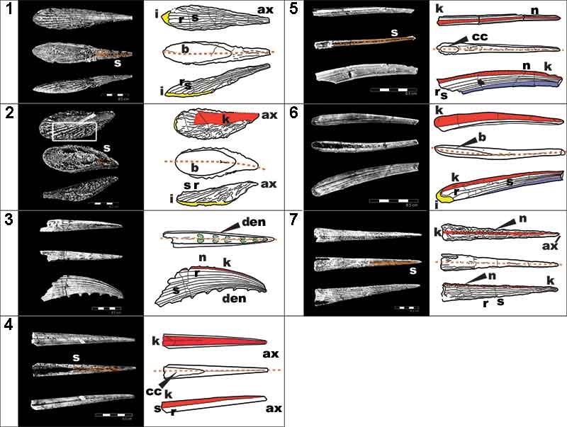
FIGURE 3. High-resolution (voxel size: 0.678 µm) synchrotron data of fin spine morphotype A. (1), virtual thin section (slice 1535) showing the general morphology and internal organization of the vascular canals and osteocyte lacunae. (2,3), segmented data illustrating the organization of vascular canals and cell spaces, and, (4,5), the reconstructed data deconstructed to show each component. (6), virtual thin sections of magnified portion of ribbing, showing the ribbing canals from slices 820, 831, and 840. Red box in (1) shows the position of the magnified portion of the fossil. Abbreviations: bvc1,2, bone vascular canals (layers 1 or 2); dvc, dentine vascular canals; o, osteocyte spaces; r, rib; rib.c, ribbing canals; s, sulcus. Scale bars equal 250 µm.
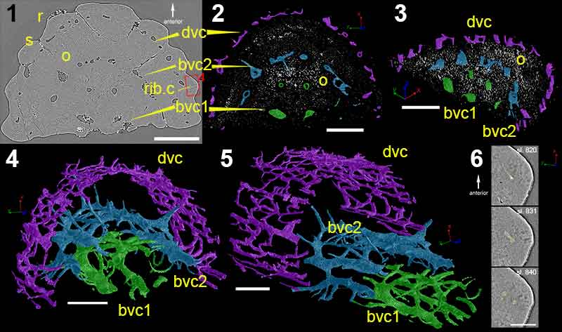
FIGURE 4. High-resolution (voxel size: 0.678 µm) synchrotron data of fin spine morphotype C, including virtual thin sections of (1), slice 1377; (2), slice 992; and (3), slice 12. (4-6) Reconstructions of the scanned fin spine showing the ornamentation. (7), Fin spine vascularization deconstructed into different parts and, (8), show all parts of the vascularization together, (9), in cross-sectional view with all canals from the scan, and (10), in cross-sectional view of isolated number of canals. (7-10) use the same colors. Scale bars equal 300 µm. Abbreviations: bas.c, basal canal; den, denticle; cc, central cavity; med.c, median canal; nod.c, node canals; r, ribbing; rib.c, ribbing canals; s, sulcus; trab.c, trabecular dentine canals.
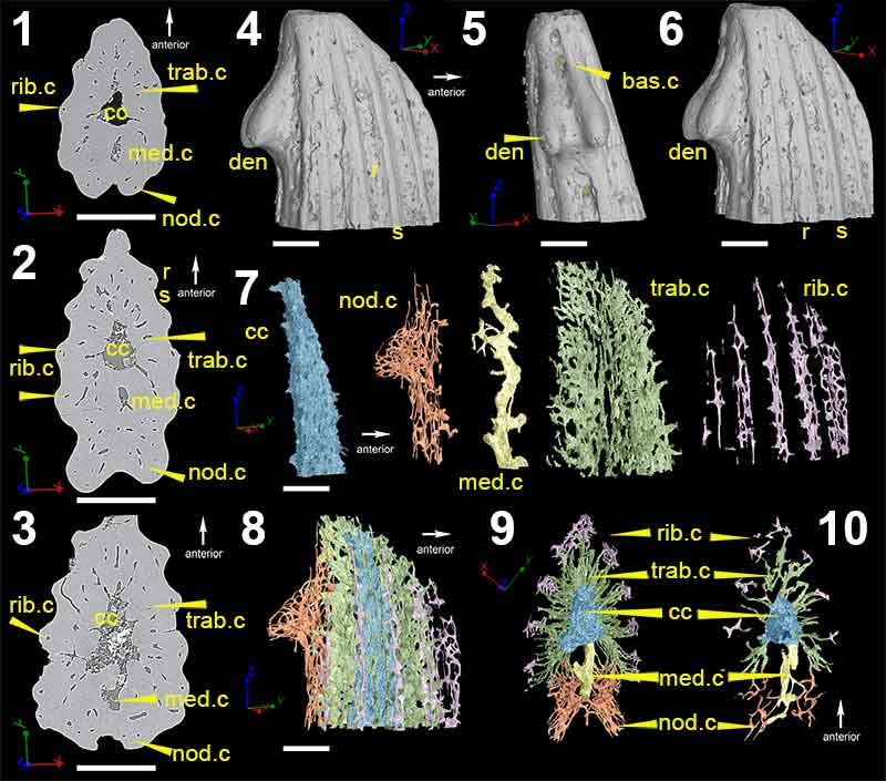
FIGURE 5. Low-resolution (voxel size: 5 µm) synchrotron data of fin spine morphotype D, including virtual thin sections of slice (1), 2596; (2), slice 2155; (3), slice 1524; (4), slice 886 and; (5), slice 222. (6), Segmented data that approximate to the scan slices 1-5, illustrating the vascularization and composition of the fin spine. (7), High-resolution (voxel size: 0.678 µm) synchrotron data 3D reconstruction illustrating the vascular organization of the fin spine. Scale bars equal 250 µm. Abbreviations: b, basal layer; cb; compact bone; cc, central canal; med.c, median canal; trab.d, trabecular dentine; vc, vascular canal.
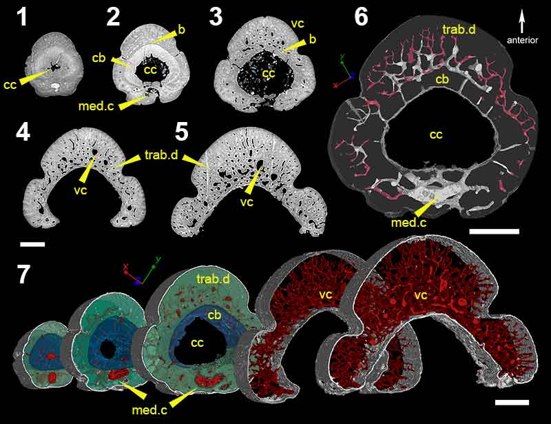
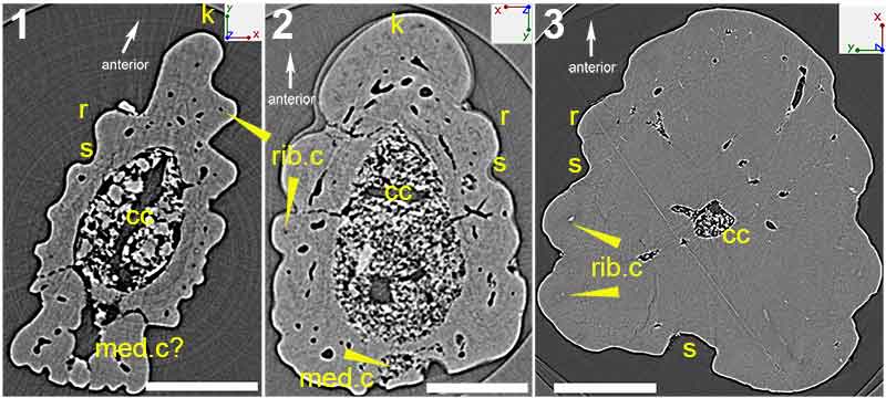
FIGURE 6. Virtual thin sections of (1), morphotype E; (2), morphotype F; and, (3), morphotype G. Scale bars equal 450 µm (1 and 2) and 200 µm (3). Abbreviations: cc, central cavity; k, keel; med.c, median canal; r, ribbing; rib.c, ribbing canals; s, sulcus.