FIGURE 1. Locality map, A) England and Wales, red box outlines locality map in (B), B) locality details, illustrating the location of Barton-on-Sea, and distribution of the Eocene Bracklesham and Barton Groups (including the Barton Beds Formation). I.O.W. = Isle of Wight.
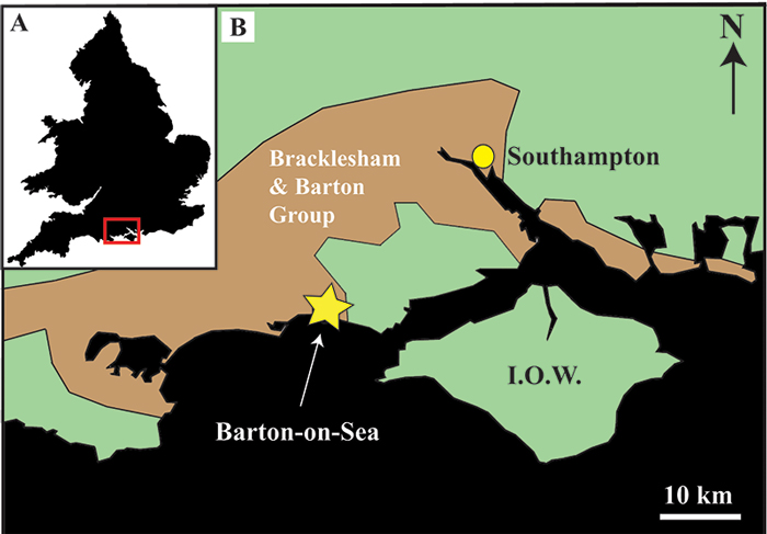
FIGURE 2. Overview, longitudinal cross-sections of Ditrupa bartonensis. A)- B) Optical images. C)-D) Scanning electron microscope, backscattered electron (BSE) images. Illustrating the two layers (1) -inner layer, and (2) -outer layer, and the overall chevron lamella character of the tube. White and black arrows indicate the position of growth lamellae within the outer (2) and inner (1) layers, respectively.
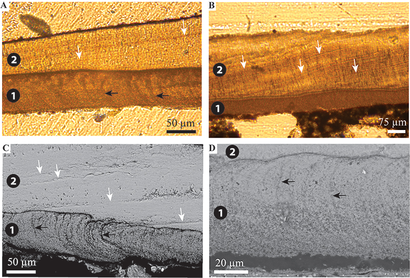
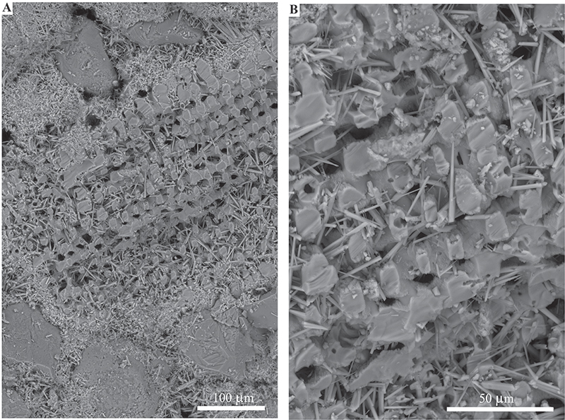
FIGURE 3. Scanning electron images of the upper structural layer from Ditrupa bartonensis. A)-D) Longitudinal views of ridged crystals. Arrows indicate locations where cleavage planes are observed (approximately perpendicular to crystal long axis) - interpreted as growth lines in Vinn et al. (2008c). Areas marked with asterisk (*) are transverse cross-sections with conchoidal fracture. In (B) area within {} is possible remnants of organic framework / membrane, expanded in (D). 1-4 in (B) highly inclined fracture packets (also see Figure 5).
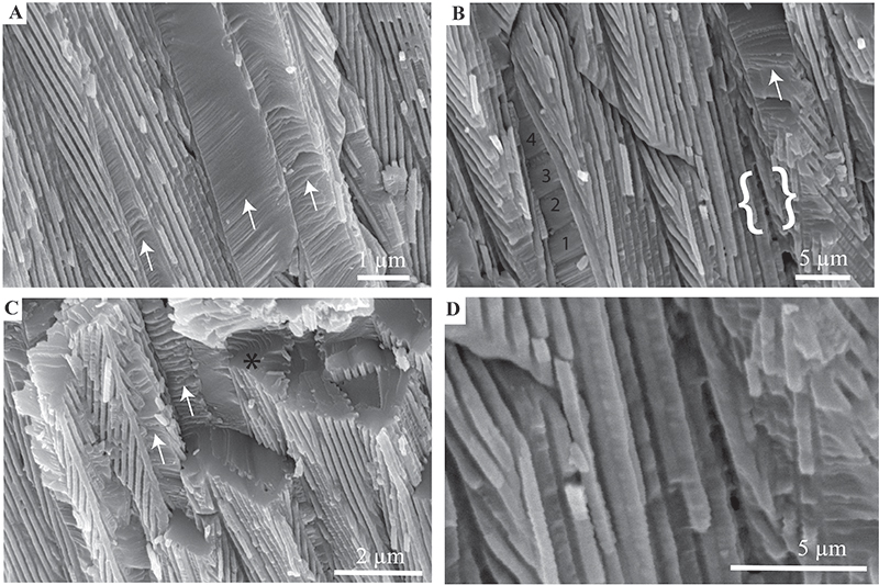
FIGURE 4. Scanning electron images of the upper structural layer from Ditrupa bartonensis. A)-F) Showing cross-sections through ridged crystals. Note that crystals commonly have triangular or wedge-shaped cross-sections, although many other highly variable shapes also occur. Also ridges range from tightly to loosely interlocking. Transverse sections appear smooth (but see Figure 5), with occasional conchoidal fractures (*).
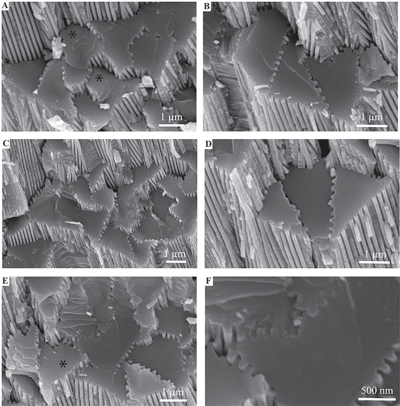
FIGURE 5. Scanning electron images of the upper structural layer from Ditrupa bartonensis. A)-C) Showing cross-sections through ridged crystals, illustrating the presence of curved (conchoidal) fractures, which have a rough uneven surface. The latter possibly reflecting the occurrence of protein vesicles. (A) shallowly inclined transverse fractures, (B) fractured surface with a fan-like pattern of conchoidal fractures, passing into rod and groove ornament. D)-F) longitudinal broken sections, illustrating irregular fracture surfaces parallel to exterior ridge and groove ornament. (D) and (E) white arrows indicate ridge and groove structure parallel to near vertical rough platey fracture (black arrow); also see Figure 3B. F) Detail of surface of near vertical rough platey fracture surface. Note images taken in low-vacuum mode, on uncoated surfaces.
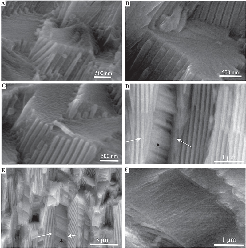
FIGURE 6. Scanning electron images of Ditrupa bartonensis. A), B) Transverse polished section through a single ridged crystal in the outer layer of D. bartonensis. A) Backscattered electron (BSE) image, B) gaseous secondary electron (GSE) image, of the same area as in (A). Illustrating what appears to be an indication of internal crystal structure. Arrows indicate the edge of the crystal. C), D) Longitudinal sections showing layer 1 (inner layer) and 2 (outer layer). Note in (D) at the interface between the layers that the regular ridged prismatic crystals each initiate from an individual point locus.
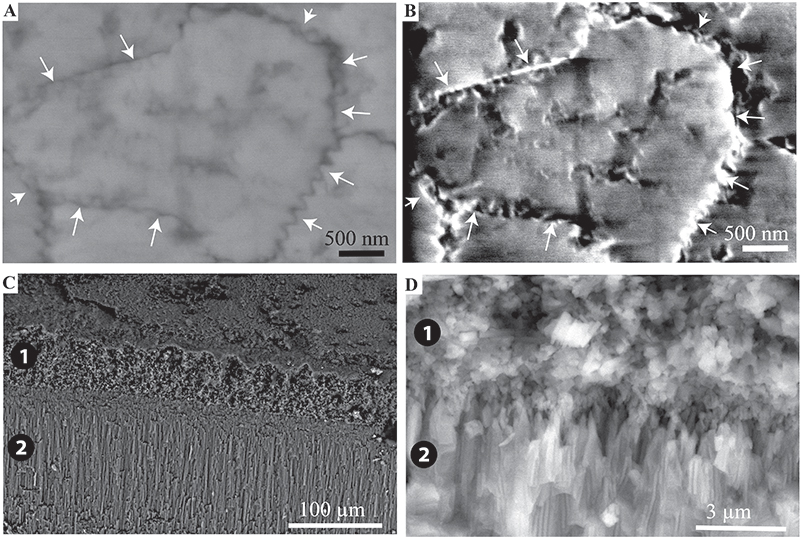
FIGURE 7. Details of the microfabric of the inner layer of Ditrupa bartonensis. A)-C) Views of the inner tube surface (arrows indicate tube long axis), with loosely arranged bundles of long slender crystals, oriented perpendicular to tube long axis (with an approximate deviation of 10˚ within the plane of lamellae). D), E) Transverse vertical section (arrow indicates direction to upper surface) with loosely arranged bundles of long slender crystals, oriented parallel to tube circumference (with a maximum deviation of ~15˚ within the plane of lamellae). In (E) prismatic crystals occur associated with granular calcite (*), of possible authigenic origin. F)-H) Longitudinal vertical section (arrow indicates direction to upper surface), with apparent granular fabric.
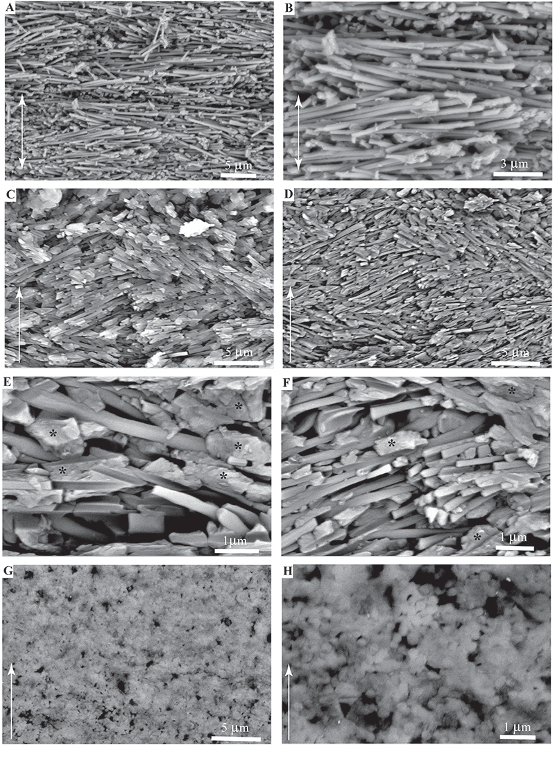
FIGURE 8. 3D reconstruction of the inner layer of Ditrupa bartonensis, illustrating fabric appearance in relationship to tube long axis (large black arrows). A) Cartoon of tube, B) virtual 3D reconstruction using micrographs.
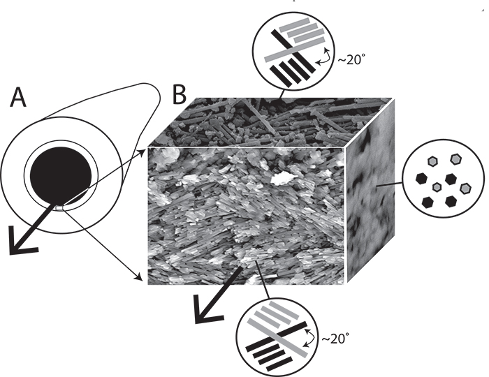
FIGURE 9. XRD trace of whole powdered tube of Ditrupa bartonensis. Illustrating the occurrence of calcite, with no other carbonate phases.
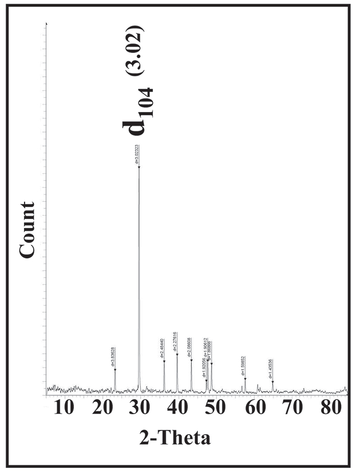
FIGURE 10. Echinoderm spine constructed from single calcite crystal. Possible analogue for formation of RRP structure. A) Overview, B) Close-up.