FIGURE 1. Anuran morphology. 1, Basic anuran anatomy. Inset picture shows an enlarged hindlimb with tubercles located on the base of the pes. 2, Scaphiopus holbrookii on the sediment surface. 3, S. holbrookii burrowing beneath the surface.
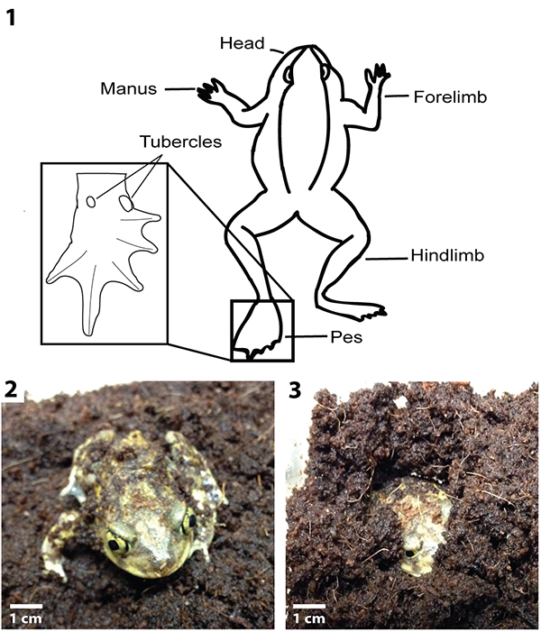
FIGURE 2. Quantitative properties of burrows. 1, Measured properties include maximum depth (D), tunnel and shaft width (w), height (h), and circumference (c), length (L), and slope (S). 2, Complexity (C) is the sum of the number of surface openings (e), segments (s), and chambers (h) of a burrow. 3, Tortuosity is a measure of the average sinuosity of all of the segments of a burrow system. The tortuosity of a single segment is calculated by dividing the length (u) by the straight-line distance (v). Modified from Hembree et al. (2012).
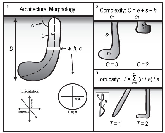
FIGURE 3. Surface feature produced by Scaphiopus holbrookii. 1, Shallow pit in the sediment surface. 2, Two separate, closely spaced burrow openings. 3, A single circular burrowing opening. 4, Excavated sediment (sand) on top of a burrow opening.
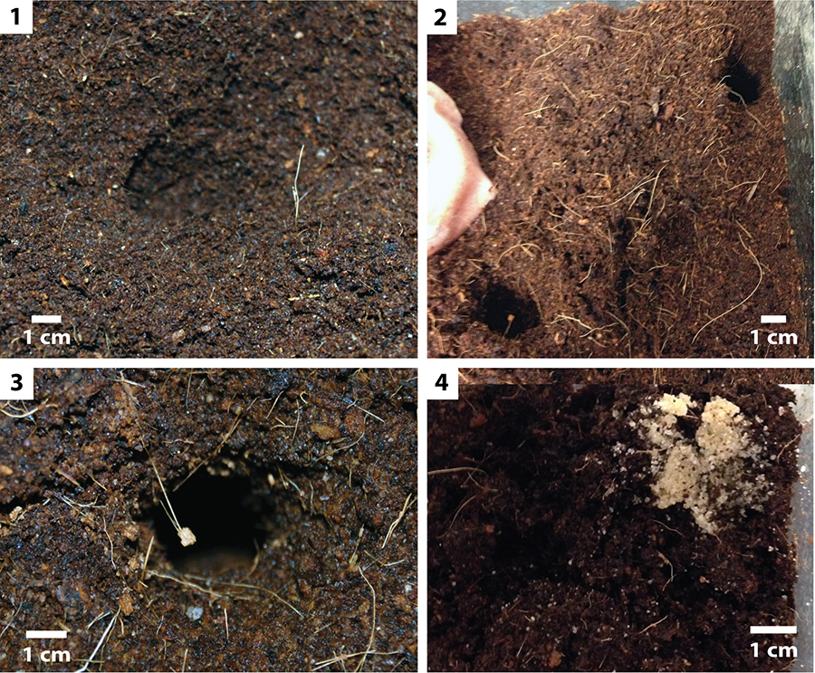
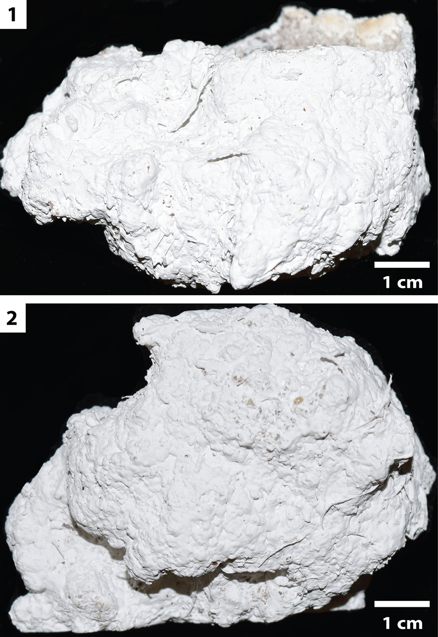
FIGURE 4. Bioglyphs produced during burrow construction. 1-2, Photo (1) and line drawing (2) of a raised ridge on the bottom of the terminal chamber (SH11). The arrows in 1 and 2 and circled area in 2 indicate the position of the ridge on the base of the chamber. 3-4, Photo (3) and line drawing (4) of an imprint of an individual’s hind limb (SH11). The arrows in 3 and 4 and circled area in 4 indicate the position of the imprint on the chamber floor. 5-6, Photo (5) and line drawing (6) of a terminal chamber showing multiple triangular protrusions (SH25). The arrows in 5 and 6 and circled areas in 6 indicate the positions of the protrusions on the chamber walls.
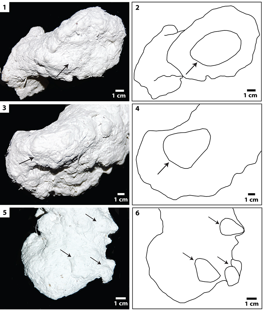
FIGURE 5. Vertical shafts with terminal chambers. 1, Side view (SH25). 2, Frontal view (SH33). 3, Side view (SH33).
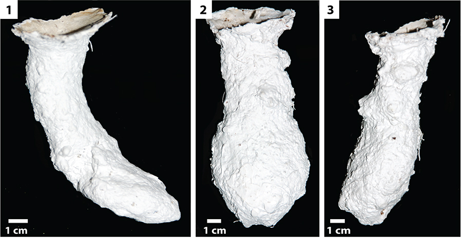
FIGURE 6. Subvertical shafts with terminal chambers. 1, View from the back of burrow (SH11). 2, Side view (SH11). 3, Side view (SH14).
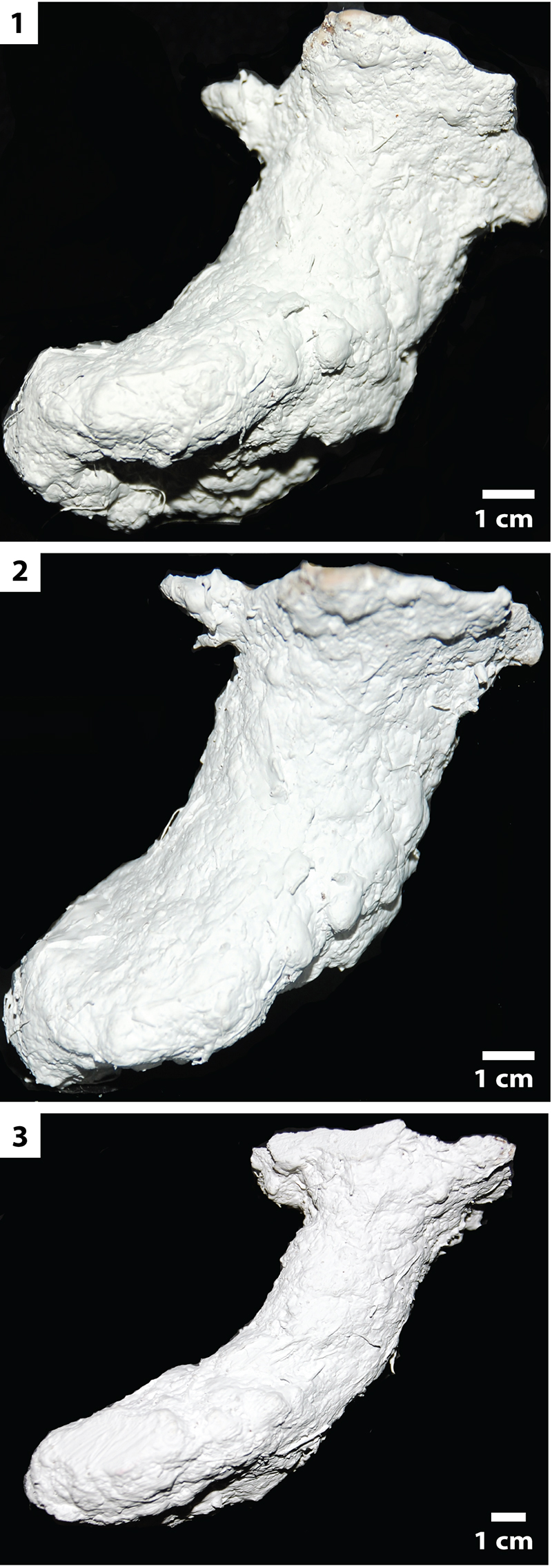
FIGURE 7. Isolated chambers. 1, Side view (SH20). 2, Frontal view (SH20). 3, Frontal view (SH67).
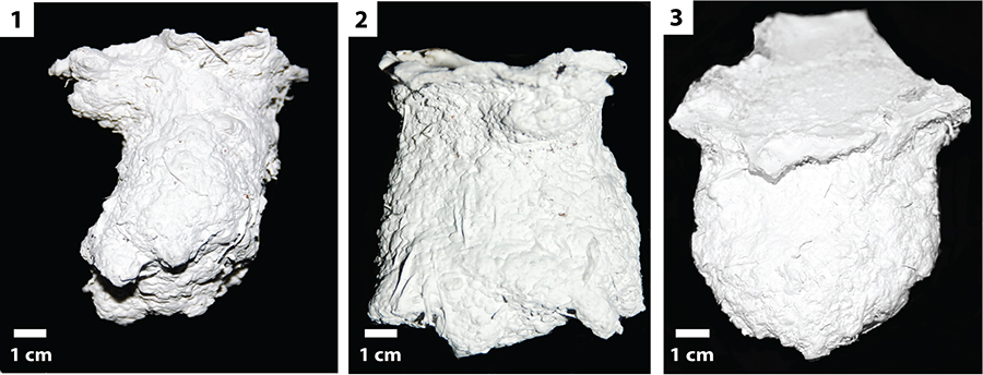
FIGURE 8. Cluster analysis of all burrows produced by Scaphiopus holbrookii. Numbers in yellow circles indicate a major cluster of burrows discussed in the text. The color of the burrow specimen number indicates the architecture of the burrow: red = vertical shafts; orange = subvertical shafts; green = isolated chambers. The similarity values of the clusters are indicated by an arrow and a number. RT = resting trace.
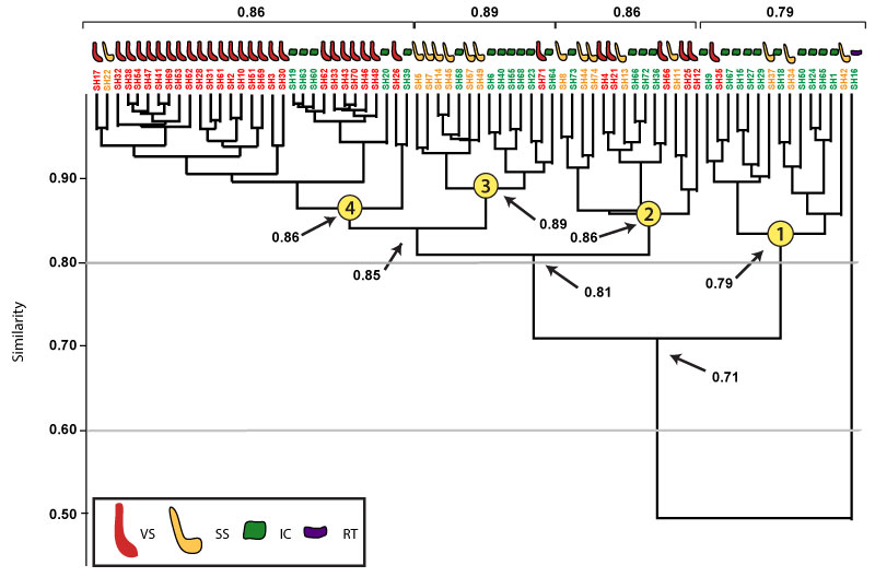
FIGURE 9. Three different species and their respective burrows produced in previous studies. 1, An emperor scorpion (Pandinus imperator). 2, A subvertical tunnel produced by P. imperator. 3, A gold skink (Mabuya multifasciata). 4, A subvertical tunnel produced by M. multifasciata.5, A tiger salamander (Ambystoma tigrinum). 6, A subvertical tunnel produced by A. tigrinum.
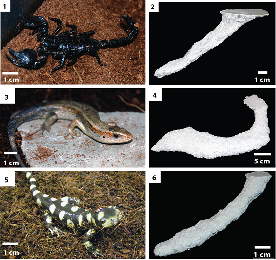
FIGURE 10. Cluster analysis of burrows produced by Scaphiopus holbrookii and Pandinus imperator. Major clusters discussed in the text are denoted with the letter of the cluster in a yellow circle. The color of the burrow specimen number indicates the tracemaker: green = S. holbrookii; red = P. imperator. The similarity values of the clusters are marked with an arrow and a number.
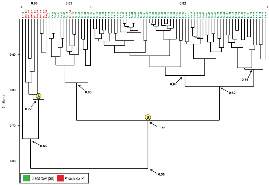
FIGURE 11. Cluster analysis of burrows produced by Scaphiopus holbrookii and Mabuya multifasciata. The color of the burrow specimen number indicates the tracemaker: orange = M. multifasciata. For additional formatting descriptions refer to Figure 10.
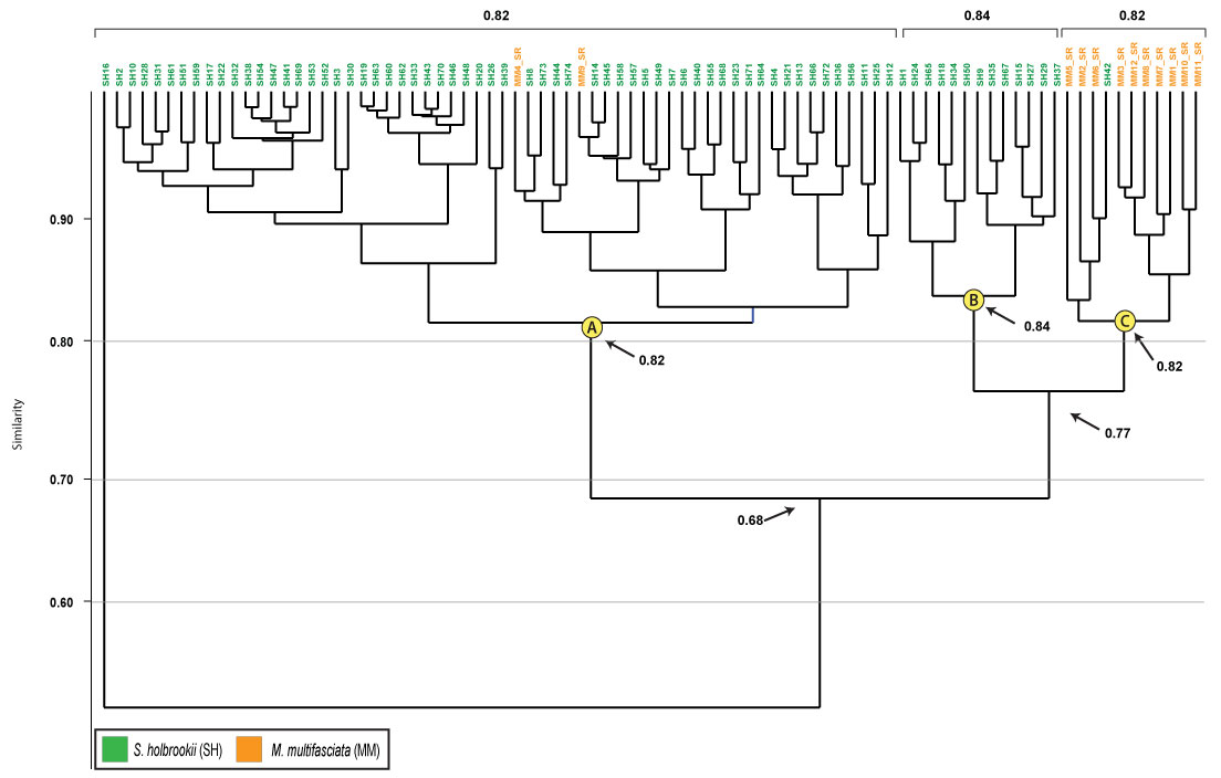
FIGURE 12. Cluster analysis of burrows produced by Scaphiopus holbrookii and A mbystoma tigrinum. The color of the burrow specimen number indicates the tracemaker: purple = A. tigrinum. For additional formatting descriptions refer to Figure 10.
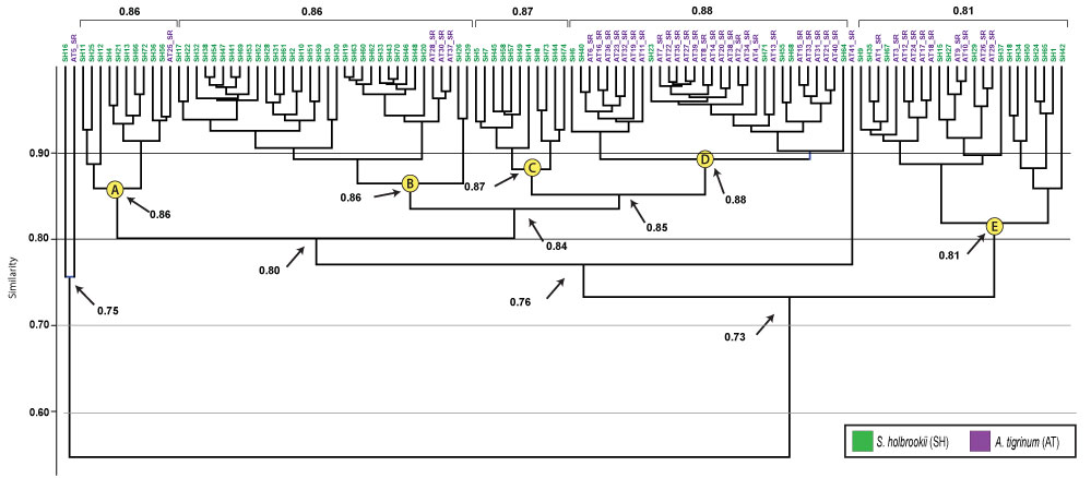
FIGURE 13. Cluster analysis of burrows produced by Scaphiopus holbrookii, Pandinus imperator, Mabuya multifasciata, and Ambystoma tigrinum. For formatting descriptions refer to the captions of Figure 10, Figure 11, and Figure 12.
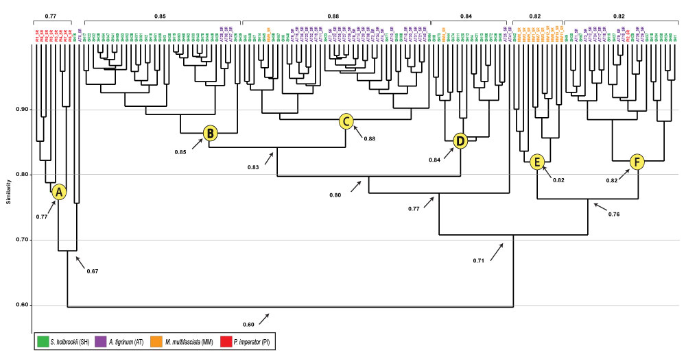
FIGURE 14. Anomalous burrow architecture (SH16) defined as a resting trace. 1, View from the side. 2, View from the bottom of the burrow.