![]()
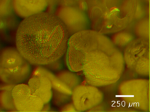
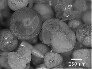
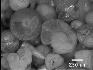
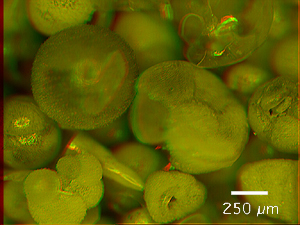
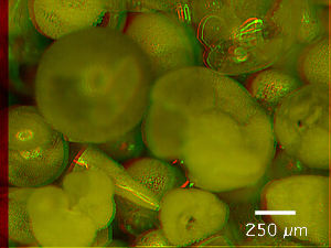
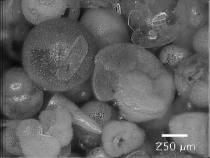
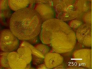
Figure 9. Matrix of images showing the construction of focus improved anaglyph images. Horizontal rows represent focal planes 1 (top) through 3 (bottom). In the lowermost row are the results after application of the focus extend macro for levels 1 through 3. In the vertical columns are images taken in left (column 1) and right (column 2) positions of the microscope and the resulting anaglyphs for each level (column 3), respectively. The image shown in the lowermost row and in column 3 is the final result. Click on images to view enlargements.
| Left
images (mono or coaxial mode) |
Right
images (stereo mode) |
Anaglyphs (stereo-vision) |
|
| Level
1 (top) |
 |
 |
 |
| Level
2 (middle) |
 |
 |
 |
| Level
3 (bottom) |
 |
 |
 |
| Fused |  |
 |
 |