MATERIALS AND METHODS
CT Scanning
The resin embedded skull (HUJ-PAL
3659) presents the ventral surface exposed on an epoxy resin plaque, retaining
traces of the original limestone matrix on the surface. The epoxy resin holding
the specimen is approximately 17.5 mm thick, 75 mm wide, and 195 mm long. The
skull was scanned at the University of Texas at Austin High-Resolution CT
Facility (tube voltage 150 kV, 0.16 mA, no filter, air wedge, 190% offset, slice
thickness of 0.24 mm, S.O.D. of 130.0 mm, 1800 views, 1 sample per view,
interslice spacing of' 0.2 mm, field of reconstruction is 70.0 mm,
reconstruction offset 600, reconstruction scale 75). This resulted in 308
transverse slices at ~137 micron interpixel resolution and a slice thickness of
240 microns; each slice was saved as a 512 X 512 pixel tiff image in both
16 bit and 8 bit modes (Appendix 1). The sequential 308 slices together form
a three-dimensional matrix, and each pixel representing a volume element (voxel) in a
three-dimensional framework. Variations in the value of each voxel represent
variations in relative X-ray attenuation, which closely mirror compositional
variations. X signifies the transverse axis, Y the dorsoventral axis, and Z the
longitudinal axis of the CT data set. Voxblast version 3.0 (VayTek 2000) was
used to build rendered and lighted isosurface and sectional reconstructions.
Voxblast was also used to resample the original 308 slice stack in the XZ plane,
in order to isolate the 93 slices that contain the specimen–thus reducing the
file size and memory requirements for processing, and providing better sectional
illustrations for comparison with isosurface reconstructions. ImageJ version
1.32i (Rasband 2003) was used for analysis and tracing of slices and Adobe
Photoshop 6.0 (Adobe Systems, Inc. 2001) for cropping and rotation of the
original data set as well as increasing voxel density using the bicubic method
of resampling. The latter process was used to optimize the isosurface
reconstruction abilities of Voxblast, providing a more voxel-dense volume,
thereby minimizing aliasing effects.
CT scanning and computer
reconstruction have resolving limitations. These are manifested in spatial
resolution, X-ray attenuation differentiation, noise artifacts, and
reconstruction artifacts. Specimen geometry greatly influences both the
available spatial resolution and artifacts caused by variation in X-ray scatter
and differential absorption due to the amount and composition of material
intersected by the X-rays at different angular rotations. Ideal specimens are
cylindrical and small enough to sit close to the X-ray source, providing
magnification via the fan beam projection onto the X-ray detectors. In the case
of HUJ-PAL 3659, specimen size and geometry were less than optimal, presenting a
long rectangular cross section, with the area of interest small relative to the
block size, thereby reducing beneficial magnification. Serial sections do not
clearly delineate individual elements but show centers of greater attenuation,
allowing elements to be traced through the volume. Additionally, software
problems encountered during the scanning process forced multiple interruptions
and restarts, resulting in slice misalignment in the anterior and midsection of
the skull and vertebral column. These misalignments are visible in the
isosurface reconstructions as transversely oriented lines on the anterior
portion of the skull and vertebral column.
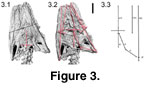 A loss of data in the midsection of
the skull occurred during one of the scan interruptions, constituting
approximately five slices and amounting to about a 1 mm gap, and is represented
by the thick black transversely oriented line across the midsection of the skull
in the CT reconstructions (Figure 3; see also
Appendix 2). The methods employed
here are not perfect; however, they provide an independent test of previous
optical and X-radiograph observations and augment our knowledge of the
morphology of this specimen. Comparison with light photographs demonstrates the
superiority of CT techniques in eliminating lighting artifacts such as shadow
and specularity, and provides a clearer illustration of topology and true
morphology (Appendix 2). Additionally, the protocols outlined retain digital
data representing a facsimile of the specimen, and therefore a testable data set
(Appendix 1). Moreover the methods described herein can be duplicated and
improved upon if so desired and therefore presents a superior level of
testability and reproduction of results compared to optical examination or
X-radiographs alone.
A loss of data in the midsection of
the skull occurred during one of the scan interruptions, constituting
approximately five slices and amounting to about a 1 mm gap, and is represented
by the thick black transversely oriented line across the midsection of the skull
in the CT reconstructions (Figure 3; see also
Appendix 2). The methods employed
here are not perfect; however, they provide an independent test of previous
optical and X-radiograph observations and augment our knowledge of the
morphology of this specimen. Comparison with light photographs demonstrates the
superiority of CT techniques in eliminating lighting artifacts such as shadow
and specularity, and provides a clearer illustration of topology and true
morphology (Appendix 2). Additionally, the protocols outlined retain digital
data representing a facsimile of the specimen, and therefore a testable data set
(Appendix 1). Moreover the methods described herein can be duplicated and
improved upon if so desired and therefore presents a superior level of
testability and reproduction of results compared to optical examination or
X-radiographs alone.
Taphonomic Distortion
Figure
3.1-3.2 display isosurface images of the dorsal and ventral surfaces of the
skull of Pachyrhachis. The ventral surface is reversed so landmarks can
be stacked in order to recognize and remove distortion (Figure
3.1, see also Appendix 3). A line from the center of the basioccipital through the
parasphenoid rostrum defines the midline of the skull (Figure
3.1). The
posterior midline of the dorsal surface indicated by the sagittal crest lies
above the ventral midline (Figure 3.2). As the skull was crushed, the snout
rotated to the left, with the right maxilla overlying the tip of the right dentary and the left dentary displaced laterally but lying on its medial
surface. The skull of Pachyrhachis is crushed dorsoventrally, with
individual elements suffering varying degrees of compaction and displacement.
The left and right postorbitals are symmetrically displaced laterally, and the
coronoid processes of the lower jaws are collapsed medially on both sides. The
symmetry of structures and their crushing patterns across the skull are
important because they indicate force applied orthogonal to the bedding plane on
which the specimen was preserved.
To quantify the amount of
displacement of each element, the ventral isosurface reconstruction was rotated
18.4 degrees relative to the original scanning axis to approximate the alignment
of the center of the parasphenoid and the posterior center of the basioccipital
(Figure
3.1) at a reference angle of 0.0 degrees. The dorsal isosurface was then
rotated -18.4 degrees to match the alignment of the ventral surface. By
comparing the dorsal sagittal alignment of the parietal to that of the
basioccipital-basisphenoid, it is clear that the braincase behaved as a single
unit with respect to crushing (Figure 3.2; see also
Appendix 3).
The parietal-basicranium midline was
used as a reference of 0.0 degrees. In dorsal view the posterior terminus of the
medial suture of the frontals is displaced slightly right of center, the suture
angles 15.5 degrees to the left anteriorly. The prefrontals approximate this
displacement to an equivalent degree. The right maxilla is preserved in a
slightly more anterior position than the left. The small edentulous premaxilla
is preserved in place between the anterior maxillaries. The right mandible is in
articulation with the distal quadrate and displaced anteriorly to the left 29.0
degrees, underlying the skull and invading the natural position of the right
ectopterygoid. The left mandible is preserved adjacent to the left side of the
skull, embracing the left maxilla.
All relative displacement of
elements including the snout, frontals, prefrontals, the left mandible, the left
supratemporal, and the sagittal crest is leftward. All rotation of elements is
counterclockwise, including the quadrates, with the left displaced medially and
slightly overlapping the anterior vertebral column.
Morphological Model
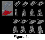 The morphological model (Figure 4.1)
was constructed by building polygon surfaced wireframe simulation elements using
Lightwave 3D, version 8 (Newtek 2004) and employing the three-dimensional isosurface model derived from the CT data as a guide. Removal of distortion from
the elements was somewhat subjective; however, care was taken to approximate
surface areas and lengths of the CT model in the proxy models of individual
elements. The proxy elements were then manipulated to determine best fit to one
another. Finally, the elements were distorted to mimic the distortion present in
the CT data representing the actual fossil by manipulating the models (Figure
4.2). The undistorted and distorted reconstructions were then used as end points
in a time sequence animation to simulate the interaction of elements
and the relative timing and effects of crushing (Figure 4.3-4.9; see also
Appendix 4 for animation sequence).
The morphological model (Figure 4.1)
was constructed by building polygon surfaced wireframe simulation elements using
Lightwave 3D, version 8 (Newtek 2004) and employing the three-dimensional isosurface model derived from the CT data as a guide. Removal of distortion from
the elements was somewhat subjective; however, care was taken to approximate
surface areas and lengths of the CT model in the proxy models of individual
elements. The proxy elements were then manipulated to determine best fit to one
another. Finally, the elements were distorted to mimic the distortion present in
the CT data representing the actual fossil by manipulating the models (Figure
4.2). The undistorted and distorted reconstructions were then used as end points
in a time sequence animation to simulate the interaction of elements
and the relative timing and effects of crushing (Figure 4.3-4.9; see also
Appendix 4 for animation sequence).
Institutional Abbreviations
HUJ, Hebrew University of Jerusalem;
UCMP, University of California Museum of Paleontology; TMM, Texas Memorial
Museum, Austin Texas; CAS, California Academy of Science.
Specimens Examined
Pachyrhachis problematicus HUJ-PAL 3659;
Cylindrophis ruffus CAS 231481; Cylindrophis ruffus UCMP 136995;
Anilius scytale TMM(VPL) M-8281; Xenopeltis unicolor TMM(VPL) M-8276;
Xenopeltis unicolor TMM(VPL) M-8277; Python regius TMM(VPL) M-8278;
Python curtis TMM(VPL)M-8279;
Epicrates cenchria TMM (VPL) M-8280.
