MATERIALS AND METHODS
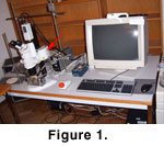 Microscope setup and hardware. For imaging a 3 CCD color video camera from Sony (model DXC 390P) is used. It is mounted on a Leica MZ 6 binocular microscope with a Leica AX stand for stereoscopic and monoscopic vision, a zoom magnification changer, and a motorized focus control (Figure 1). The camera produces images at a resolution of 752 (horizontal) by 582 (vertical) pixels. The camera and the motor focus are connected to a PC running under Windows 2000 that is equipped with an internal four-axis (OASIS-4i) controller board from Objective Imaging. The OASIS-4i board allows, next to controlling the motorized microscope focus, the connection of three additional devices that can be driven by stepping motors.
Digital imaging software. The imaging system runs with AutoMontage Pro version 5.01a software from
Syncroscopy (Synoptics Group). It automatically captures images at a series of predefined focal depths during a vertical scan of the microscope. The software allows the user to select the number of vertical increments at which images are taken. Vertical scanning of images through the focal range and alignment of images is very fast. For example, image capturing from 50 vertical levels the system requires no more than about 80 seconds, and image alignment and montaging them takes another 45 seconds, which is a great advance over the system described in
Knappertsbusch (2002). This system is useful for the construction of stereographic anaglyph images from microscopic objects without stepped surfaces that would occur if too few focal planes are included. AutoMontage allows the user to choose from a variety of algorithms for image montage, which enables one to adapt to the different nature of surface roughness of the objects.
 Improved illumination techniques. Direct illumination can introduce disturbing reflections from the slide, on which the object is mounted.
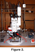
Bengtson (2000) and authors referenced therein demonstrate the usage of cross-polarized light to be very effective for enhancing contrast in digital imaging fossils. In our case, a polarizing filter is placed in the light path of the microscope objective, and a pair of polarizing filter caps is fixed on the arm tips of a swan-neck fiber optics (Figure 2). If a near vertical illumination body is attached to the microscope, a single polarizing filter plate can be glued to the microscope end of the fiber-optics cable in order to arrive at the same effects. Twisting the fiber-optics cable allows one to adjust the polarized light to extinction if necessary. These arrangements filter out glare from the background or from the object itself, and at the same time enhance the contrast between the object and the background dramatically. Tests have confirmed that insertion of a polarizing filter in the light path of the microscope does slightly shift the image reproduced on the computer monitor, but has no effect on the magnification of the image.
Improved illumination techniques. Direct illumination can introduce disturbing reflections from the slide, on which the object is mounted.
Bengtson (2000) and authors referenced therein demonstrate the usage of cross-polarized light to be very effective for enhancing contrast in digital imaging fossils. In our case, a polarizing filter is placed in the light path of the microscope objective, and a pair of polarizing filter caps is fixed on the arm tips of a swan-neck fiber optics (Figure 2). If a near vertical illumination body is attached to the microscope, a single polarizing filter plate can be glued to the microscope end of the fiber-optics cable in order to arrive at the same effects. Twisting the fiber-optics cable allows one to adjust the polarized light to extinction if necessary. These arrangements filter out glare from the background or from the object itself, and at the same time enhance the contrast between the object and the background dramatically. Tests have confirmed that insertion of a polarizing filter in the light path of the microscope does slightly shift the image reproduced on the computer monitor, but has no effect on the magnification of the image.
High magnification causes loss of light due to increased attenuation of the light, which can be compensated by stronger illumination. Particularly high constrast of calcareous microfossils against a dark background is obtained if sideward illumination is applied. This contrast enhancement occurs because calcareous microfossils are often slightly translucent, which causes differential extinction under crossed polarizing filters, similar to birifringent minerals in petrographic thin sections.
 Determination of the depth of focus as a function of magnification. Extended focus images are built from a stack of images at focal planes ranging from the object's base plane to its top. Focal planes represent volumes with a thin but finite thickness depending on the magnification and/or the numerical aperture used. For image composition at extended focus the neighbouring focal volumes must have a certain overlap in order to fully cover the object's topography. Theoretically, the ideal number of images is obtained at the Nyquist criterium, e.g., if the vertical thickness of the focal volumes
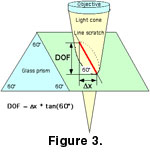
 z is half the depth of focus (Meyer, personal commun., 2003). The depth of focus of our imaging system is therefore estimated with an equilateral triangular glass prism where a straight line was scratched in the surface (Figure 3). While placing the prism under the microscope the depth of focus (DOF) is estimated by measuring the horizontal projection
X of the line that appears in focus at various magnifications:
z is half the depth of focus (Meyer, personal commun., 2003). The depth of focus of our imaging system is therefore estimated with an equilateral triangular glass prism where a straight line was scratched in the surface (Figure 3). While placing the prism under the microscope the depth of focus (DOF) is estimated by measuring the horizontal projection
X of the line that appears in focus at various magnifications:
DOF (in µm) = X * tan60°
x is given in micrometers. It can be estimated from the distance measured in pixels on the computer monitor by multiplication with a calibration factor, which converts pixels into micrometers for a particular magnification.
 Ideal vertical step interval for optimum focus montaging.
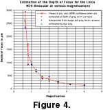
Figure 4 illustrates the relationship between the depth of focus and magnification for the Leica MZ 6 binocular with a 1x achromatic objective lense inserted. It shows a mean depth of focus range between 120 to 170µm if a typical magnification is set between 3.2x and 4x at the magnification changer body of the microscope. The ideal vertical step interval of acquiring images at these magnifications is between 60 to 70 µm. If another magnification changer body and/or a different objective are used (for example the magnification changer body of the Leica MZ 12 and/or a 1x apochromatic lense) the ideal vertical step interval needs to be estimated separately.
Ideal vertical step interval for optimum focus montaging.
Figure 4 illustrates the relationship between the depth of focus and magnification for the Leica MZ 6 binocular with a 1x achromatic objective lense inserted. It shows a mean depth of focus range between 120 to 170µm if a typical magnification is set between 3.2x and 4x at the magnification changer body of the microscope. The ideal vertical step interval of acquiring images at these magnifications is between 60 to 70 µm. If another magnification changer body and/or a different objective are used (for example the magnification changer body of the Leica MZ 12 and/or a 1x apochromatic lense) the ideal vertical step interval needs to be estimated separately.
