

Article Search
Volume 27.1
January–April 2024
Full table of contents
ISSN: 1094-8074, web version;
1935-3952, print version
Recent Research Articles
See all articles in 27.1 January-April 2024
See all articles in 26.3 September-December 2023
See all articles in 26.2 May-August 2023
See all articles in 26.1 January-April 2023
Julia L. Molnar Department of Veterinary Basic Sciences and Structure and Motion Laboratory
The Royal Veterinary College, AL97TA
United Kingdom
Julia Molnar received her MA in biological and medical illustration at Johns Hopkins University in 2009. She joined the Structure and Motion Lab in 2009 as a Scientific Illustrator and research technician. In 2010 she began a PhD in the evolutionary biomechanics of early tetrapods and crocodylomorphs. Her research interests include fossil reconstruction, 3D modelling, and biomechanics.
Stephanie E. Pierce University Museum of Zoology
Department of Zoology
University of Cambridge
Cambridge, CB2 3EJ
United Kingdom
and
Department of Veterinary Basic Sciences and Structure and Motion Laboratory
The Royal Veterinary College, AL97TA
United Kingdom
Stephanie Pierce received her PhD from Bristol University (2007) which focused on assessing the interplay between skull shape variation and biomechanical performance in extant and extinct crocodiles. Stephanie is currently a post-doc on a NERC funded project entitled “Locomotion in the earliest tetrapods: testing models of terrestriality” in the Museum of Zoology, Cambridge and at the Royal Veterinary College. Stephanie's scholarly interests are focused on assessing the link between form and function of the vertebrate skeletal system – especially with respect to muscle/skeletal interactions during feeding and locomotor behaviours in modern and extinct animals.
Jennifer A. Clack Department of Zoology
University of Cambridge
Cambridge, CB2 3EJ
United Kingdom
Jenny Clack FRS is a vertebrate palaeontologist at Cambridge University, UK. She did her PhD at the University of Newcastle upon Tyne (1984). Her research area is the origin, phylogeny and radiation of early tetrapods and their relatives among the lobe-finned fish, the "fish-tetrapod" transition, and the evolution of terrestrially. She is best-known for her book Gaining Ground: The Origin and Early Evolution of Tetrapods, published in 2002.
John R. Hutchinson Department of Veterinary Basic Sciences and Structure and Motion Laboratory
The Royal Veterinary College, AL97TA
United Kingdom
John R. Hutchinson did his PhD at the University of California (Berkeley) in Integrative Biology in 2001, followed by a fellowship in Biomechanical Engineering / bioinformatics at Stanford, then started at the RVC as a Lecturer in Evolutionary Biomechanics in 2003 in the Department of Veterinary Basic Sciences and was promoted to Reader in 2008, then Professor in 2011. His interests are in the evolutionary biomechanics of locomotion, especially in large terrestrial vertebrates. He has studied birds, extinct dinosaurs and their relatives, elephants, crocodiles, felids, and now early tetrapods, using a diversity of techniques from basic morphology to experimentation and computer modelling/simulation.
FIGURE 1. Locations of 18 biological and geometric landmarks on a neural spine (NS) of Acanthostega. Landmarks on intercentrum (IC) and pleurocentrum (PC) not shown. The locations of these points on the template specimen determine the placement of vertices in the final reconstruction. Note that the majority of the chosen landmarks lie along the edges of four local planes: anterior, posterior, medial, and lateral; this will simplify model creation (next section).
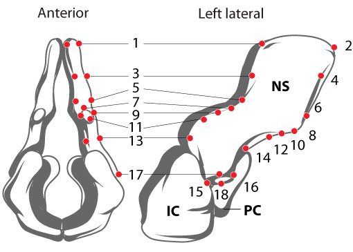
FIGURE 2. Original specimen of Acanthostega gunnari (MGUH f.n. 1227). Arrow points to neural arch of the vertebra that was used for the reconstruction.
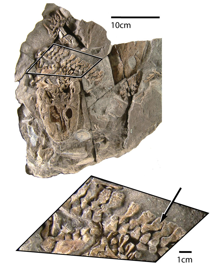
FIGURE 3. Vertebral elements segmented in Mimics from a micro-CT scan of MGUH1227. Neural spine (green), intercentrum (blue), and pleurocentrum (red) volume-rendered using the "Medium" setting (134,369 vertices). Only the left half of the vertebra is preserved, and the pleurocentrum has been taken from an adjacent vertebra.
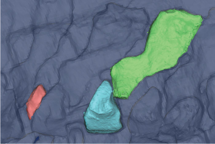
FIGURE 4. Mapping landmarks onto the scan data and planning curve placement on a neural spine of Acanthostega. 4.1, edges of major planes (blue lines); 4.2, landmarks (red dots); 4.3, perpendicular contour lines (violet); 4.4, subsidiary contour lines (green). Major plane contours define the anterior, posterior, medial, and lateral surfaces. Landmark points are located at the boundaries of major planes and structures such as neural spines, zygapophyses, and transverse processes. Perpendicular contours passing through corresponding landmark points create a grid on the surface of the template, and subsidiary contours describe the geometry of the lateral and medial surfaces of the neural arch.
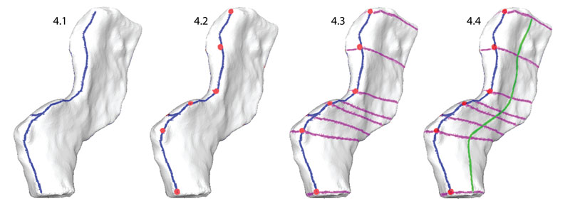
FIGURE 5. Creating contour curves. Using the Edit points curve tool, knots were placed along the contour lines (blue and green) using a setting that constrained them to the surface of the template mesh at the intersections with perpendicular lines (purple). Note that each curve has the same number of knots.
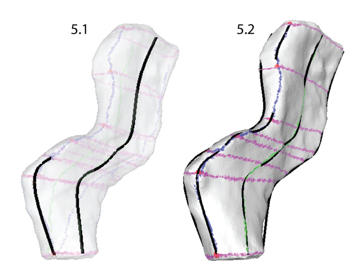
FIGURE 7. Lofting curves to create a NURBS surface. Contour curves were selected sequentially moving around the circumference of the template mesh. The curves were lofted to create the NURBS surface representing the left half of a neural spine of Acanthostega (80 knots).
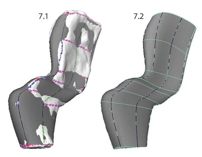
FIGURE 9. Adjusting the placement of the spline knots on the template surface. Knots were moved along the surface of the template mesh (on the left; still "Live") by dragging in the center of the Move manipulator. The NURBS surface (right) is updated automatically to reflect changes in the shapes of the curves.
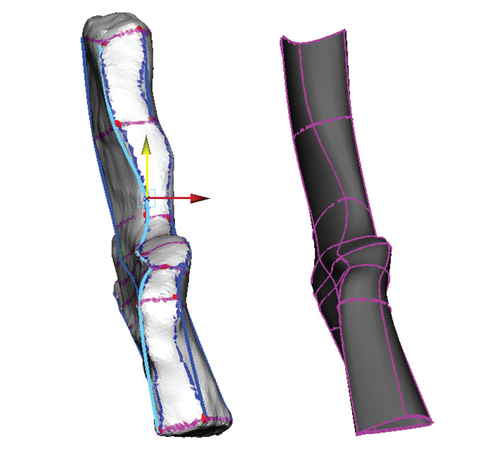
FIGURE 10. Reconstruction of the medial surface using reference images. The template mesh is hidden, and the NURBS shape (grey) created from the lofted curves has been moved to the left. NURBS curves (blue) are in the center, and the reference image is on the right (Coates, 1996, figure 9c). Knots are moved using the Move tool (yellow/green arrows). The shape of the NURBS surface is updated dynamically with changes in the shapes of the curves.
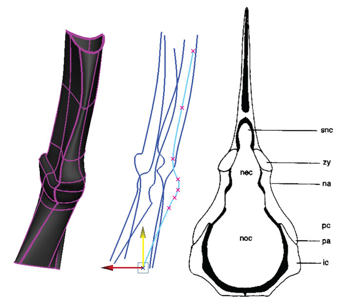
FIGURE 11. Creating the rib facet. 11.1, the curve forming the edge of the NURBS surface was duplicated twice and its pivot point was centered; 11.2, one duplicate curve was scaled to 0 and a Loft was performed between the two curves; 11.3, the resulting NURBS surface was attached to the original surface.
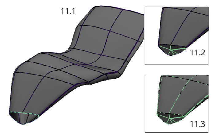
FIGURE 13. Mirroring and attaching bilaterally symmetrical elements. 13.1, neural spine, intercentrum and pleurocentrum were grouped and duplicated; 13.2, the group was mirrored across the x-axis (scaled by -1); 13.3, the intercentrum halves were attached at the midline.
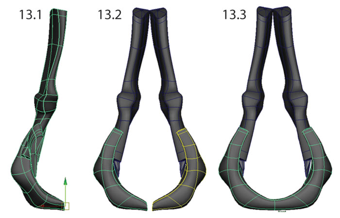
FIGURE 15. Landmarks placed for validation. 162 landmarks were used for each model: four two-point linear measurements (D1, D2, D3, D4) and six patches (P) - three on the lateral surface and three on the medial surface - composed of nine landmarks and 16 semi-landmarks each (P1-3 shown; P4-6 are on the opposite side).
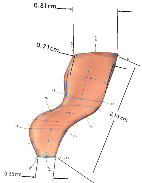
FIGURE 16. Final reconstructions of a dorsal vertebra of Acanthostega. 16.1, left lateral view; 16.2, anterior view; 16.3, posterolateral view.
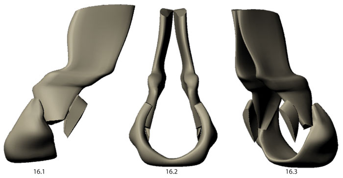
FIGURE 18. Box and whisker plot showing variation within four linear measurements taken from 15 neural arch models: D1 - neural spine width at tip, D2 - neural spine width at base, D3 - transverse process width at tip, D4 - total neural arch height.
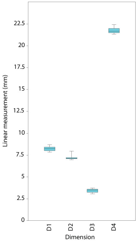
FIGURE 19. Generalized Procrustes Superimposition of landmark points showing variation in landmark position between models.
FIGURE 20. PCA showing shape differences along PC1 and PC2 between neural spine models created by different operators and the original specimen. Green diamonds represent models created by the experienced operator, blue square and pink circles the inexperienced operators and the black cross represents the original specimen. Visualization of extreme morphologies along PC1 and PC2 shows little variation between landmark configurations.
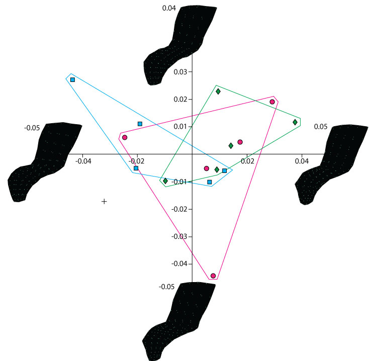
FIGURE 6. Video showing process of creating contour curves.
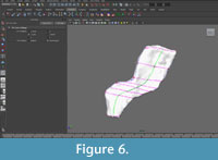
FIGURE 8. Video showing process of lofting curves to create a NURBS surface.
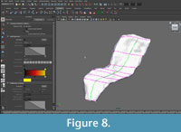
FIGURE 12. Video showing process of creating the rib facet.
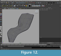
FIGURE 14. Video showing process of mirroring and attaching bilaterally symmetrical elements.
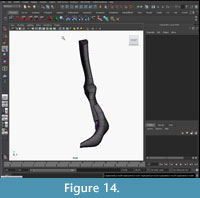
FIGURE 17. Animation showing 3D model of a dorsal vertebra of Acanthostega.
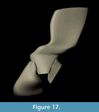
TABLE 1. Linear measurements in millimeters taken from the original specimen and each model in Landmark. The measured dimensions were: neural spine width at tip (D1), neural spine width at base (D2), transverse process width at tip (D3), and total neural arch height (D4).M=
| D1 | D2 | D3 | D4 | |
|---|---|---|---|---|
| Original | 8.54 | 7.17 | 3.61 | 22.09 |
| JLM_01 | 8.08 | 7.08 | 3.58 | 21.30 |
| JLM_02 | 8.34 | 7.02 | 3.56 | 21.56 |
| JLM_03 | 8.51 | 7.12 | 3.08 | 21.80 |
| JLM_04 | 8.67 | 7.26 | 3.42 | 21.31 |
| JLM_05 | 8.44 | 7.14 | 3.47 | 21.46 |
| SEP_01 | 8.17 | 7.93 | 3.52 | 21.32 |
| SEP_02 | 8.02 | 6.95 | 3.31 | 21.94 |
| SEP_03 | 8.22 | 6.94 | 3.22 | 21.70 |
| SEP_04 | 7.97 | 6.95 | 3.72 | 21.64 |
| SEP_05 | 8.27 | 7.20 | 3.57 | 21.44 |
| JRH_01 | 7.83 | 7.05 | 3.49 | 21.66 |
| JRH_02 | 7.86 | 7.08 | 3.08 | 22.30 |
| JRH_03 | 7.95 | 7.16 | 3.15 | 22.40 |
| JRH_04 | 8.41 | 7.10 | 3.65 | 21.98 |
| JRH_05 | 8.23 | 7.16 | 3.33 | 21.96 |
| Model average | 8.20 | 7.14 | 3.41 | 21.72 |
| Highest value | 8.67 | 7.93 | 3.72 | 22.40 |
| Lowest value | 7.83 | 6.94 | 3.08 | 21.30 |
Procedures used to create models in Autodesk Maya. Conventions used to describe Maya procedures are as follows: "Bold": denotes a menu set, "Regular>" denotes a menu bar selection, and "'Italics'" denotes a dialog box setting.
|
Creating NURBS models in Autodesk Maya |
|
|
Task |
Procedure |
|
Divide a bilaterally symmetrical mesh along its mid-sagittal plane and remove one half. |
Polygons: Edit mesh>Cut Faces tool>Options; "Delete cut faces"). |
|
Mapping landmarks onto the 3D surface |
|
|
Create a UV map |
Polygons: Create UVs>Automatic Mapping; right-drag> "Object Mode" to return to object mode). |
|
Use the 3D Paint tool to mark landmarks and contours on the mesh |
Rendering: Texturing>3D Paint Tool>Options Tool Settings>File Textures>Attribute to paint>Color; File Textures>Assign/Edit Textures>"Assign/Edit Textures" Tool Settings>Flood>Color: "white"; Flood> "Flood Paint" Tool Settings>Color>Color: "blue" Adjust brush size (Tool Settings>Brush>Radius [U]) |
|
Creating contour curves |
|
|
Make mesh "Live": |
Modify>Make Live |
|
Create NURBS curves using the Edit Points Curve Tool |
Create>EP Curve Tool>Options; degree setting: "3 Cubic"; knot spacing: "Chord length" |
|
Lofting to create NURBS shapes |
|
|
Select all curves one by one moving circumferentially around the vertebral element |
Toolbar>Select tool; Shift-click. (Note: although any curve may be selected first, it is important to select the curves sequentially moving around the surface of the template mesh.) |
|
Loft curves to create a NURBS surface |
(Surfaces: Surfaces>Loft>Options) using the following settings: Parameterization (controls how the interpolation is handled and whether the surface will be a closed loop): "Chord length"; "Auto reverse"; "Close"; Surface degree (the degree of the polynomials used to calculate the surface): "Cubic"; Output geometry (type of geometry created): "NURBS". All other settings were left at defaults (Figure 6). |
|
Adjustments and extrapolation of missing surfaces. |
|
|
Slide knots along the surface of the template mesh |
Select curve, right-click and drag to select "Edit points"; select Edit point with Move tool and click and drag on the center of the Move manipulator (Figure 7). |
|
Adjusted knots without snapping to mesh |
Same as above, but drag arrows of Move tool rather than center. |
|
Create closed facets |
|
|
Duplicate edge curve |
Surfaces: Edit curves> Duplicate surface curves; click to select open edge |
|
Duplicate again |
Edit>Duplicate |
|
Scale one duplicate to a single point |
Modify>Center pivot; Attribute editor: "Scale X: 0", "Scale Y: 0", "Scale Z: 0" |
|
If necessary, move point to center of the open edge |
Move tool |
|
Loft new curves |
Shift-click to select, Surfaces>Loft |
|
Attach facet to NURBS shape |
First select facet, then Shift-click to select NURBS shape (order is important!); Edit NURBS>Attach Surfaces>Options; Attach method: "Blend"; Blend bias: "0," "Insert knot," Insert parameter: "1.0") (Figure 9). |
|
Mirroring and attaching |
|
|
Group all elements |
Shift-click to select; Edit>Group |
|
Mirror |
Edit>Duplicate; scale by a factor of -1 in the X direction (Attribute editor: "Scale X: -1", "Scale Y: 1", "Scale Z: 1") |
|
Attach halves at mid-line |
Shift-click to select; Surfaces: Edit NURBS>Attach Surfaces>Options: Attach method, "Connect"; Multiple knots, "Remove." (Figure 10) |
|
Alternative techniques |
|
|
Create polygonal models |
Create>EP Curve Tool>Options, degree setting: "Linear"; knot spacing: "Chord length"; output geometry: "Polygons" |
|
Partially automate knot insertion |
Surfaces: Edit Curves>Insert Knots>Options>Insert location: "Between selections." "Multiplicity" setting determines how many knots will be inserted within each span |
Idealized landmark-based geometric reconstructions of poorly preserved fossil material: a case study of an early tetrapod vertebra
Plain Language Abstract
We describe a method for building idealized digital models of fossil bones in 3D modeling software. The models can be used for visualization or further research. To demonstrate the method, we build an idealized model of a vertebra from a prehistoric animal.
Resumen en Español
En paleontología y antropología se usan frecuentemente los modelos digitales en tres dimensiones (3D) de la morfología de los huesos.
Como los fósiles a menudo son fragmentarios o están deformados suele ser necesario, por razones estéticas o prácticas, crear una versión idealizada de esqueletos digitales. En este artículo proponemos un método para reconstrucciones geométricas basadas en puntos morfométricos (landmarks) de huesos fósiles en software de gráficos 3D mediante el uso de datos de tomografía computarizada o escáner láser como plantilla. Este método no requiere un software especializado ni una particular destreza artística. Permite controlar la densidad local de la malla, especificar los puntos morfométricos importantes y los planos principales, eliminar grandes huecos y estructuras extrañas y ajustar de forma interactiva la imagen 3D mediante el movimiento de unos pocos vértices para corregir deformaciones tafonómicas menores. El resultado es un modelo simple, ilustrativo y preciso que puede ser usado para diversas aplicaciones analíticas y de visualización, incluyendo reconstrucciones de fósiles incompletos, modelos estancos para el cálculo de la masa y de la posición del centro de masas, mallas de base para la deformación de placas delgadas (TPS) e imágenes intermedias en una serie completa mediante “morphing”. Para ilustrar el método, lo hemos aplicado a la reconstrucción de una vértebra dorsal del tetrápodo primitivo Acanthostega gunnari. Hemos contrastado la validez de nuestro método mediante comparaciones morfométricas lineares y geométricas de nuestras reconstrucciones con los datos de escaneo originales y entre tres operadores distintos. La desviación media de los modelos con respecto al original, basada en cuatro medidas lineales, es mínima, lo que demuestra que el método preserva las proporciones del fósil original. No hemos hallado diferencias de forma estadísticamente significativas entre los modelos construidos con operadores diferentes, por lo que se puede concluir que el método es repetible.
Palabras clave: Acanthostega; modelos idealizado; esqueleto digtal; reconstrucción de fósiles; modelado NURBS; visualización.
Traducción: Miguel Company
Résumé en Français
Reconstruction géométrique idéalisée de matériel fossile mal préservé à partir de points repères : le cas d’étude d’une vertèbre de tétrapode
Les modèles numériques en trois dimensions (3D) de la morphologie des os sont fréquemment utilisés en paléontologie et anthropologie. Du fait que les fossiles sont souvent cassés ou déformés, il devient souvent nécessaire, pour des raisons esthétiques ou pratiques, de créer une version idéalisée du squelette numérique. Nous proposons une méthode pour créer une reconstitution géométrique des os fossiles sur la base de points de repère dans un logiciel graphique 3D, en utilisant les données de balayages tomodensitométriques ou laser comme calibrage. Cette méthode ne nécessite ni logiciel spécialisé, ni expertise artistique. Elle permet le contrôle de la densité locale de sommets, la spécification de points de repère importants et de plans majeurs, l’élimination de larges trous et de structures étrangères, et un ajustement interactif de la forme 3D en bougeant un petit nombre de sommets pour corriger les déformations taphonomiques mineures. Le résultat est modèle simple, explicatif, et fidèle qui peut être utilisé dans diverses applications analytiques et graphiques, incluant la reconstitution de fossiles incomplets, des modèles étanches pour l’approximation de masses et centres de masse, la reconstruction d’une surface spline à partir d’une surface triangulée, et des intermédiaires dans une série incomplète via « morphing ». Pour démontrer l’efficacité de la méthode, nous l’avons appliquée à la reconstruction d’une vertèbre dorsale d’un tétrapode basal, Acanthostega gunnari. Nous avons validée notre méthode par des comparaisons morphométriques linéaires et géométriques de notre reconstruction avec les données originales du balayage et ce pour trois différents opérateurs. Sur la base de trois mesures linéaires, la déviation moyenne de nos modèles d’avec l’original était minimale, montrant que la méthode conserve les proportions du fossile original. Nous n’avons trouvé aucune différence de forme statistiquement significative entre nos modèles construits par les différents opérateurs, prouvant ainsi que la méthode est reproductible.
Mots clés : Acanthostega; modèle idéalisé; squelette numérique; reconstruction de fossile; modélisation NURBS; visualisation.
Translator: Olivier Maridet
Deutsche Zusammenfassung
Idealisierte Orientierungspunkt-basierte geometrische Rekonstruktionen bei schlecht erhaltenem Fossilmaterial: eine Fallstudie über den Wirbel eines frühen Tetrapoden
Digitale dreidimensionale (3D) Knochenmorphologie- Modelle werden in der Paläontologie und Archäologie oft genutzt. Da Fossilien häufig fragmentarisch oder deformiert erhalten sind, ist es oftmals nötig eine idealisierte Version eines digitalen Skelettes zu erstellen, entweder aus ästhetischen oder praktischen Gründen. Wir schlagen eine Methode vor, mit der Orientierungspunkt-basierte geometrische Rekonstruktionen von fossilen Knochen in 3D Graphics Software erstellen werden können indem CT-oder Laserscan-Daten als Vorlagen genutzt werden. Diese Methode verlangt keine spezialisierte Software oder explizites Fachwissen. Sie erlaubt die Kontrolle der lokalen Netzdichte, die Spezifikation von wichtigen Orientierungspunkten und Hauptebenen, die Elimination von großen Lücken und Fremdkörpern und interaktive Anpassung der 3D Form indem durch Bewegung einer geringen Anzahl von Eckpunkten kleinere taphonomische Deformationen korrigiert werden können. Ergebnis ist ein einfaches, illustratives und genaues Modell, das für diverse analytische und visuelle Anwendungen inklusive der Rekonstruktion von unvollständigen Fossilien, hieb-und stichfesten Modellen für Massen-und Massenschwerpunktsermittlung, Basenvernetzung für Thin-Plate-Spline Verzerrung und Zwischenprodukt in einer unvollständigen Serie via „Morphing" genutzt werden kann. Um diese Methode zu veranschaulichen, wendeten wir sie bei der Rekonstruktion eines Dorsalwirbel des basalen Tetrapoden Acanthostega gunnari an. Wir validierten unsere Methodik mit linearen und geometrischen morphometrischen Vergleichen unserer Rekonstruktionen sowohl gegen die originalen Scandaten als auch zwischen drei verschiedenen Bedienern. Die durchschnittliche Abweichung der Modelle vom Original war minimal, beruhend auf vier lineare Messungen. Dies zeigt, dass die Methode die Proportionen des Originalfossils bewahrt. Es gab keine statistisch signifikante Formabweichung zwischen den Modellen der verschiedenen Bediener, was zeigt, dass die Methode reproduzierbar ist.
SCHLÜSSELWÖRTER: Acanthostega; idealisiertes Modell; digitales Skelett; Fossilrekonstruktion; NURBS-Modellierung; Visualisierung.
Translator: Eva Gebauer
Arabic
Translator: Ashraf M.T. Elewa
Polski Abstrakt
FAUNA I EKOLOGIA POKŁADU ZE STRZYKWAMI, LLANDRINDOD, WALIA, UK (DARRIWIL, ŚRODKOWY ORDOWIK) I NAJSTARSZE ARTYKUŁOWANE STRZYKWY
W przeciwieństwie do kambryjskich lagerstätten, wyjątkowo zachowane fauny ordowiku na ogół różnią się znacząco od siebie pod względem składu taksonomicznego, co sugeruje znacznie większe zróżnicowanie paleośrodowisk podczas tego interwału czasowego. Niejasne jest jednak, jak wielki stopień ekologicznego zróżnicowania ordowiku wynika z nietypowych facji bądź udziału zespołów w wyjątkowo zachowanych faunach. W artykule tym opisujemy nowe lagerstätten z Walii zachowane dzięki wysokiemu tempu sedymentacji oraz wczesnej pirytyzacji, datowane na środkowy ordowik (darriwil, biozona Hustedograptus? teretiusculus). Wstępne analizy opisywanej fauny, biorące pod uwagę nową metodologię przekładania zachowanej liczebności różnych grup na szacunkowe wartości obfitości życia, wykazały że fauny pozornie zdominowane przez trylobity faktycznie były zdominowane przez ramienionogi, gąbki retikulinowe i protomonaksonidowe, oraz paleoskolecidy z karpoidami i strzykwami równie licznymi jak trylobity. Przy normalnych warunkach tafonomicznych zespół ten wydawałby się w zapisie kopalnym być typową fauną mułowcową ordowiku, wskazując iż reprezentuje względnie normalny zespół otwartomorski. Omawiany biotop nie przypomina żadnej opisanej do tej pory fauny ordowiku, co sugeruje znaczny stopień ukrytego zróżnicowania zespołów tego wieku. W skład tego wyjątkowego zespołu taksonomicznego wchodzi najwcześniejszy artykułowany przedstawiciel Holothuria, Oesolcucumaria eostregen. et sp. nov., o globularnej postaci z częściowo uszkieletowionym układem ambulakralnym.
Translators: Dawid Mazurek and Robert Bronowicz
-
-
-
Review: The Princeton Field Guide to Mesozoic Sea Reptiles
 The Princeton Field Guide to Mesozoic Sea Reptiles
Article number: 26.1.1R
April 2023

 Poster Winners 2024