|
|
|
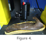
METHODSEdmontosaurus materialThe cranial material used for scanning is from Canadian Museum of Nature (CMN) specimen number 2289, a paratype of Edmontosaurus regalis. The specimen was recovered by C.H. Sternberg in 1916 from the Edmonton Formation along the Red Deer River, "seven miles west and north of Morrin" (Lambe 1920, p. 2). The head skeleton is mostly complete and exceptionally well-preserved. The skull is relatively undistorted and is only missing the predentary and premaxillae. The suspensorium (e.g., quadrates, palatal elements) were found disarticulated from the braincase. For this study, the braincase and available left-side elements were selected for scanning. The left-side elements were favored because they were more complete than those of the right side. Arius 3-D laser scannerThe elements were scanned using an Arius 3-D laser scanner. The laser system characterizes each scanned point from the surfaces of the object according to its color and location in three-dimensional space. It does this by scanning the surface of an object using one focused laser beam comprising three wavelengths (red, green, and blue), and recording the reflected light using a charge couple device. Each point on the object is described by six numeric values; three positional values X, Y, and Z, and three surface color values R, G, and B. The X coordinate of each point on the object is calculated from an accurate measurement of the position of the scanning mirror in the camera. The Y coordinate is calculated from an accurate measurement of the camera motion system. The Z coordinate is calculated through laser triangulation within the camera. At the same time color information at each point is gathered by measuring the intensity of the reflected laser beams. Color intensity measurements are accurate, being completely independent of ambient light. The total light exposure is about 3.5 milliwatts, roughly equivalent to shining a flashlight on the object. The laser light moves continuously at about 300 mm/sec across the surface of the object therefore the dosage of light on the specimen's surface is extremely small.
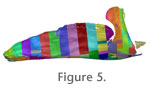
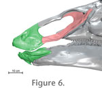
Once the complete point-cloud model was created, it was converted into a triangulated polymesh comprising thousands of individual faces using surfacing software (Paraform v3.1, 2001). Compared to the number of points in the original point-cloud, the number of triangles in the original converted polymesh is roughly double. For example the dentary (scanned at 400µm resolution) contained 2.2 million points and when converted to polymesh it yielded 4.4 million triangles. Models with such heavy computations require too much processing power and memory to be practically used in animation software. Therefore the face count in the polymesh models for all the scanned elements was reduced. For example the braincase was scanned at 500µm and yielded 1.1 million points and 2.2 million polymesh triangles that were then reduced to 100,000 triangles. The resulting element was much lighter to work with but still maintained its geometry. Other elements that were reduced substantially include the splenial, nasal, ecopterygoid, and palatine. Elements, or parts of elements, whose surfaces could be involved with cranial kinesis (e.g., upper and lower toothrows, pterygoid, jugal, quadratojugal) were not reduced as much. For example, in its reduced state, the maxillary tooth row comprised 100,000 polymesh triangles. Assembling the model. The reduced-size polymesh skull-components were imported into the animation software 3-D Studio Max v. 8 (3ds Max; Autodesk 2006) as object files and digitally assembled to form the skull. Right-side elements that were not scanned (see above) were constructed in the animation software by creating a mirrored clone of the left-side elements. Most of the CMN 2289 skull components were fit together with little difficulty. One exception was the pterygoid, which initially did not fit well lengthwise within the skull. Given that the pterygoid is a very thin element, it was likely deformed post-mortem. For this model, the pterygoid was fit to the skull by slightly shortening the quadrate ramus of the pterygoid. For future versions of the model the question of how best to correct for deformation of the pterygoid will be explored more fully. There is also evidence of some deformation within the braincase. Examination of the braincase in anterior view (e.g., see Lambe 1920, figure 7) shows the bottom of the braincase is sheared slightly to the right. For this study the basipterygoid processes were shifted slightly back toward the left so that they were more symmetrical. Also uncertain in the model is the mediolateral position of the lower tooth rows relative to the uppers. For the current model the dentaries were positioned by aligning the upper and lower tooth rows so that the Edmontosaurus model is isognathous, as per the assumptions of the original pleurokinetic-hinge hypothesis (see above). The resulting configuration shows a small space between the anterior tips of the dentaries. Unfortunately, with the CMN 2289 predentary missing, it is difficult to ascertain whether this configuration of the dentaries is reasonable. Future studies will examine the morphology of the predentary region in hadrosaurs in more detail in order to better constrain the positioning of the dentaries.
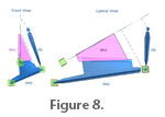
Inverse kinematics. This is a tool often used in animation to recreate accurate limb movements. It is a method of determining how the linked elements of a system must move in order to produce a desired outcome movement. It is based on a bottom-up hierarchal approach where the child element controls the movement of the parent in the linked system. For example, the human arm is a hierarchal linked system that can be animated (without IK), by positioning the linked elements individually, starting from the parent of the system (e.g., upper arm) down to the last child of the hierarchal linked system (hand). In IK, the human arm is animated/moved by using the last child of the hierarchal linked system (hand) to determine the position of the upper elements of the arm (Autodesk Canada 2006). Figure 8 shows how the IK approach effectively recreates the adduction of the mandible and retraction of the quadrate observed in the pleurokinetic model presented in Weishampel (1984). In the Edmontosaurus 3-D model presented here, the mandible and quadrate were treated as a linked system because they shared a common pivot point (i.e., at the jaw joint). The child of the system is the mandible, and the parent is the quadrate. Given that the mandible and quadrate are linked as a hierarchal system, the quadrate was moved by manipulating the position of the mandible. The 3-D rig with the attached polymesh skull components was mobilized using two types of animation methods: Inverse kinematics (IK) and a wiring system. These two approaches were used to ensure that the primary movements, including their rotational magnitudes presented in the original hypothesis (see Corythosaurus animation in Figure 3) were replicated in the Edmontosaurus model. The wiring system was used to link the maxilla and quadrate, whereas the mandible and quadrate were linked by inverse kinematics. In the Corythosaurus model, the maxilla and quadrate are shown abducting simultaneously (Weishampel 1984, figure 20a). However, the degree of rotation of the quadrate and maxilla differ: In anterior view the rotation of the maxilla is greater than that of the quadrate (see Table 1). Weishampel (1984, p. 79) suggested that differences in rotation should be possible because the "palatine pterygoid articulation in hadrosaurids modifies the degree to which the quadrates are forced laterally and caudally by lateral rotation of the maxillae." Yet, the maxilla and quadrate are also attached via the jugal and quadratojugal. Thus, the movements of the maxilla and quadrate are linked medially by intervening palatal elements (i.e., palatine and pterygoid) and laterally by lateral facial elements (i.e., jugal, quadratojugal). For the maxillary abduction to be greater than the quadrate there has to be movement through both the medial and lateral linkage systems. Lateral facial elements would have to disarticulate. For example the jugal would be pulled rostrolaterally from the quadratojugal. Such a pattern of lateral disarticulation was not described as part of the original model (Weishampel 1984). We, therefore, incorporated the simplifying assumption that the lateral facial skeleton should function to ensure that the rotation of the maxilla and the quadrate would be matched in magnitude. Wiring system. In the Edmontosaurus model, the maxilla and quadrate were linked using an animation technique referred to as a wiring system. A wiring system is an animation technique that creates a relationship between two or more elements so that any change in position or orientation made in the parent element (e.g., the maxilla) is translated to the child element(s), (e.g., the quadrate) (Autodesk Canada 2006). The wiring system linked a point near the posteroventral margin of the maxilla to a posteroventral point on the quadrate, so that when the maxilla was moved manually the quadrate moved in response. It is possible to move both the maxilla and quadrate manually; however the wiring system was used here to automate the model for the testing phase. As mentioned above, only the mandible, maxilla, and quadrate polymesh components were attached to the rig. The braincase, nasals, and premaxilla were not attached to the rig, but were simply held stationary within the animation world space. The jugal and palatine were attached rigidly to the maxilla, so these three elements functioned as a single, solid object. The assumption that these elements would be a single functional unit is reasonable considering their shared attachment surface is large and complex. The various elements forming the mandible were also treated as a single rigid object. In order to accommodate the quadrate retraction described in the original hypothesis (Figure 3) it was necessary to allow some mobility in the facial skeleton of the model. In particular, as the quadrate retracts, it should move away from the maxilla so that one or both of the intervening joints (i.e., the jugal-quadratojugal and/or quadratojugal-quadrate contacts) disarticulate. To simplify the model, we arbitrarily chose to fix the quadratojugal to the quadrate. The jugal and quadratojugal were left unconnected so that as the quadrate retracted separation could occur only between the quadratojugal and jugal. It is important to keep in mind that any observed separation between the quadratojugal and jugal should be taken to indicate that there is separation between elements somewhere along the chain of lateral facial elements. The pterygoid contacts the basipterygoid process, palatine and quadrate. In this model these attachments were not rigid. Rather, as the palatine and quadrate moved through the powerstroke, the position and orientation of the pterygoid was adjusted "manually" so that, first, connections were maintained between the pterygoid and its contacting elements, and second, there was no interference between the pterygoid and the surrounding elements. Assumptions of the model. As in any model, animation models are necessarily simpler than their real-world counterparts. For research purposes, the simplifying assumptions used in the model should be matched to the research question. In this study, the model was developed to investigate the intracranial movements that may have occurred during chewing. Thus the focus of this model is on bony interactions among the cranial elements and occlusal surfaces of tooth rows. To investigate intracranial movements, we assumed that the braincase and parts of the facial skeleton were immobile, whereas particular joints in the palate and face were not. Mobile connections along the face were prevented from being displaced mediolaterally relative to one another, while being allowed some rostrocaudal separation. This constraint seems acceptable because most of these joints overlap mediolaterally. The remaining cranial elements were allowed to be mobile, allowing those movements resulting from mandibular adduction and maxillary abduction to occur. Some of the assumed mobility, such as that seen at the otic and basal joints, is similar to that found in many birds and squamates (Zusi 1993; Herrel et al. 1999; Metzger 2002). The synovial morphology of these joints in hadrosaurs suggests that these may also have been mobile (Weishampel 1984). On the other hand, the model also assumes mobility within the facial and palatal skeleton (e.g., quadrate-quadratojugal, pterygoid-palatine). The occurrence of smooth joint-surfaces in the face of dinosaurs has led many researchers to infer sliding motion between them (e.g., Weishampel 1984; Bakker 1986; Rayfield 2004). Although facial mobility is present in some birds (e.g., some parrots developed synovial jugal-maxillary articulations) and snakes, the presence of mobility in the facial sutures of non-avian dinosaurs and most other diapsids remains uncertain (Holliday 2006), and the functional link between suture morphology and intracranial mobility is largely unexplored. It is beyond the goals of this study to analyze the morphological basis for cranial kinesis, and we allowed the potential for movement to occur at all of these joints during the experiment. |
|