FIGURE 1. Lateral and dorsal profiles of Allosaurus (MOR 693) used for 3D reconstructions. Air spaces are color coded as transparent objects; colors may appear darker where the rendering of the bone is darker. Lines labeled as C represent cervical (neck) segments associated with respective cervical vertebrae, as S represent divisions of the skull and head. E=ear, C=cervical, S=skull.
Specific landmarks: E1 and E2, intermediate segments of the middle ear cavity. C2-1, posterior of these vertebrae and the skull, except the retroarticular process. S1, top of parietals. S2, anterior edge of visible jaw muscles. S3, posterior edge of orbit. S4, posterior edge of lacrimal. S5, anterior edge of lacrimal's jugal ramus, posterior edge of antorbital sinus. S8, anterior extent of antorbital sinus. S10, anterior extent of bony nostril.
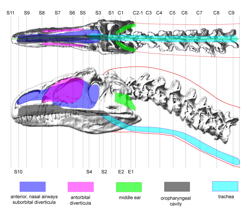
FIGURE 2. The dynamics model of Allosaurus (MOR 693), visualized with CT skeletal data from Adams registered with the Solid Edge model of its fleshed-out geometry. Compared with Figure 1, lofting in Solid Edge has caused a bulge behind the parietals. TD=tracheal diameter; note the cutout in the anterior neck segment at TD=7 cm (as in Figure 7). The interior, purple objects are air spaces. The blue sphere is at the COM of the head, and yellow spheres and coordinate systems are for centers of mass for neck segments. The Z over each neck COM designates the transverse, Z axis of Solid Edge's coordinate system for the COM.
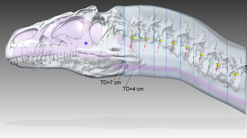
FIGURE 3. Dorsal oblique view of external geometry of the head and neck of Allosaurus, showing the lofted cutout in the head segment to accommodate the segment for cervical vertebrae 1 and 2 (C1–2). Elements of the model's geometry were positioned relative to the origin and axes of the global coordinate system (lower right). The colored sphere indicates the head's center of mass.
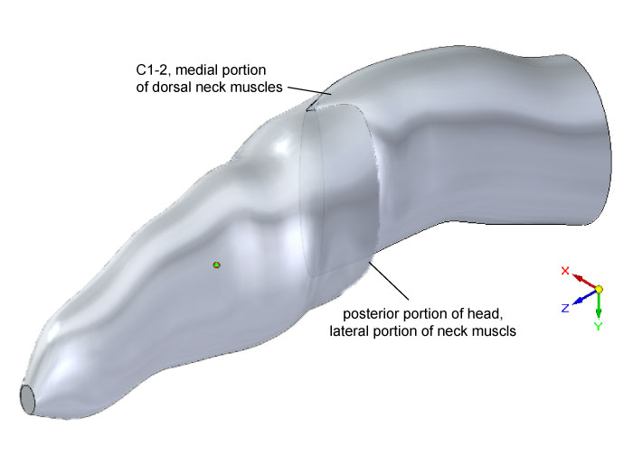
FIGURE 4. (1) Lateral view of the modeled head geometry of Allosaurus depicting air spaces in place; the antorbital diverticulum (air sac) is superficial in position and in a darker color. The small sphere locates the COM of the remaining head tissue. (2) Air spaces within the head of Allosaurus. The middle ear space (pharyngotympanic sinus) extends from the eardrum to the braincase. The constricted laryngopharynx/anterior trachea is an artifact of the lofting procedure in Solid Edge.
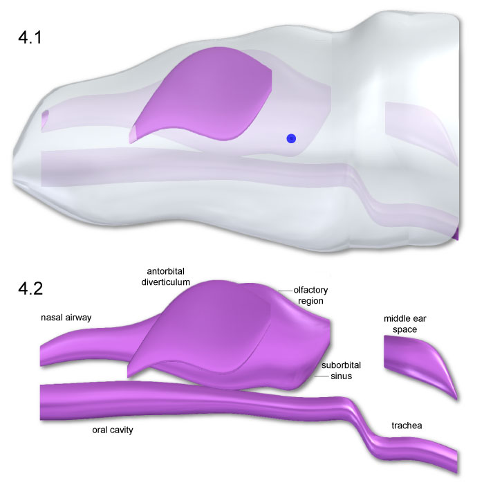
FIGURE 5. Dorsal (1 and 2) and ventral (3 and 4) views of Allosaurus head and air space geometry. The blue spheres locate the head COM Slight dorsomedial inclination of the antorbital diverticula (2 and 3) was necessary to enclose the structures within the head.
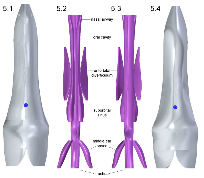
FIGURE 6. Head geometry of Allosaurus is shown in anterior (1) and posterior (2) views, with blue spheres representing centers of mass for head tissues. Air spaces in the same respective views (3, 4) depict slight medial inclination of the antorbital diverticula.
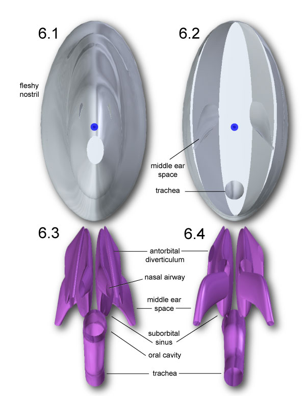
FIGURE 7. Centers of mass (yellow spheres) for neck segments of Allosaurus, determined for tracheal diameters of 6.768 cm (1) and 4 cm (2). The COM for each segment is slightly more ventral with 4 cm trachea. The 6.768 cm trachea scallops out the anterior of segment C1-2 (1) at the left of the model. Note that the axes (x,y,z) are equivalent to (y,z,x) in the Adams model and Table 2,Table 3, and Table 4.
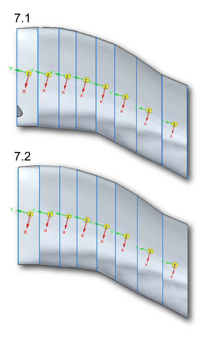
FIGURE 8. Ventroflexor insertions on the occiput of Allosaurus (MOR 693). Abbreviations:
MLCS=musculus longissimus capitis superficialis. MLCP=musculus longissimus capitis profundus. MRCA=m. rectus capitis anterior/ventralis. CR=center of rotation, on the occipital condyle.
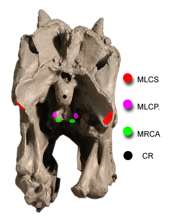
FIGURE 9. Reconstruction of head ventroflexors of Allosaurus (MOR 693) in lateral (1, 3) and dorsal (2, 4) views, with abbreviations from Figure 8. In (2) and (4), the ventroflexors m. longissimus capitis profundus (MLCP) and m. rectus capitis anterior/ventralis (MRCA) are ventral to the vertebrae.
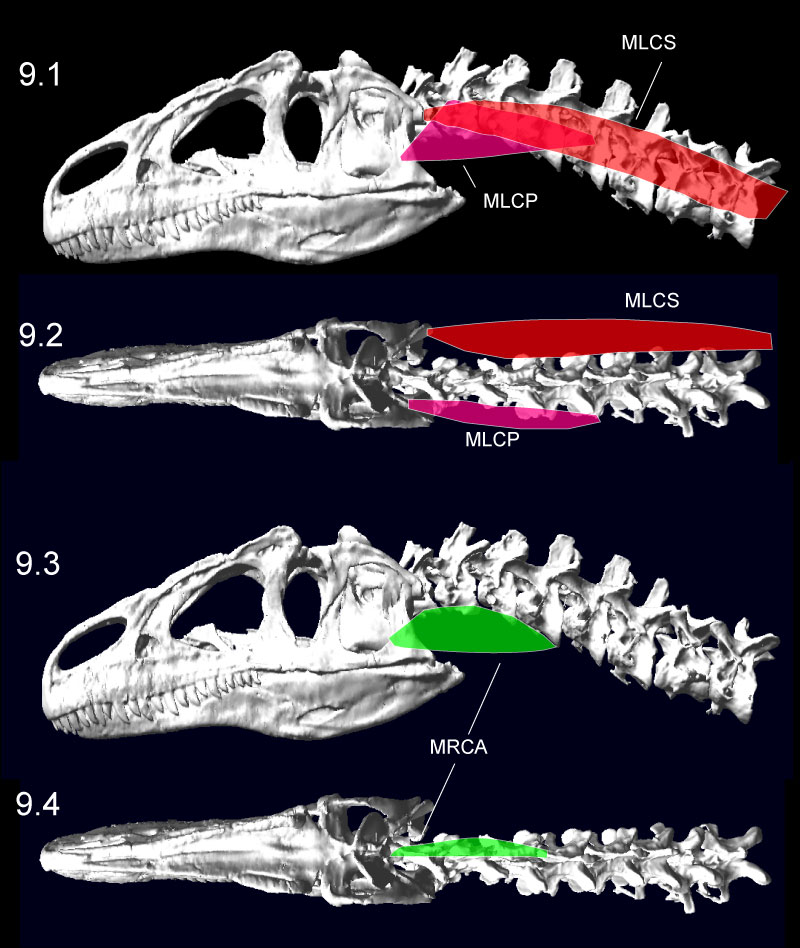
FIGURE 10. Dorsiflexion (1) and ventroflexion (2) of the Allosaurus (MOR 693) model in MSC Adams, minimizing disarticulation of the zygapophyses. The head could ventroflex at a steeper angle than simulated here (Figure 13). The transparent sphere within the cranium was used to position skull center of mass. Click on image to see animation.
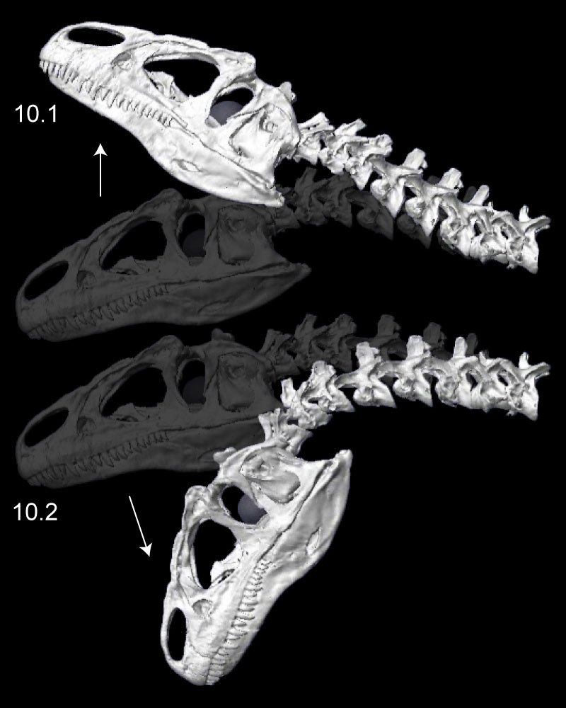
FIGURE 11. Left lateroflexion of the head and neck of Allosaurus (MOR 693), with slight right-turned (1), intermediate (2), and fully lateroflexed (3) poses. In the initial pose (1), the head and all cervical vertebrae are in posterolateral view. Note relative rotation and reasonable overlap of zygapophyses in all poses.
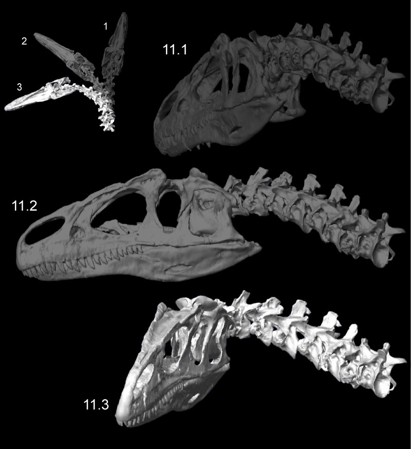
FIGURE 12. Retraction (1) and protraction (2) of the head and neck of Allosaurus (MOR 693), from kinematic simulations. The white arrows at neural spines show primary angular movements of vertebrae in retraction. The transparent sphere within the cranium was used to position skull center of mass. Click on image to see animation.
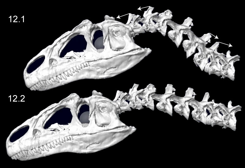
FIGURE 13. Ventroflexion simulated on the skull of Allosaurus (MOR 693). The rows indicate simulation time. The columns are for the initial position of each simulation, endpoints for gravity acting alone, m. longissimus capitis superficialis acting alone, and for all ventroflexors acting together. The coordinate axes (lower left) are as in Table 3, for x (transverse), y (dorsoventral), and z (anteroposterior) directions; movement about these axes are for pitch (simulated here), yaw, and roll, respectively. The white arrows indicate displacement magnitudes of the tip of the snout from the initial position in the x direction. Muscles are modeled as line-of-sight tensile forces (thin red lines) from origin to insertion.
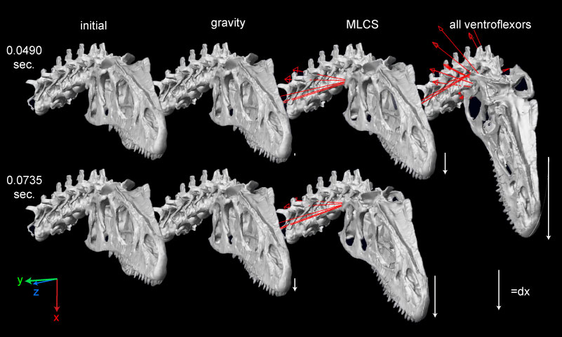
FIGURE 14. Ventroflexive movement of the anterior tip of the cranium of Allosaurus, plotted against time and including the point's vertical position (dx). 1 and 2 plot linear (acm, vcm) and angular ( cm,
cm,  cm) accelerations and velocities with all ventroflexors activated. 3 and 4 plot the same quantities with contraction of m. longissimus capitis superficialis (MLCS).
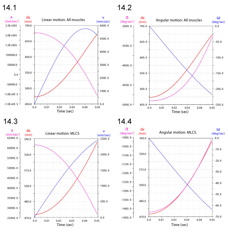
FIGURE 15. Linear displacements dx (1), velocities v (2), and accelerations a (3) of a point at the anterior tip of the premaxilla of Allosaurus. Subscripts refer to simulations with gravity alone, all ventroflexors (all), and just m. longissimus capitis superficialis (MLCS).
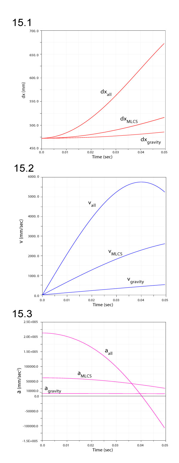
FIGURE 16. Comparison of angular velocities (1) and accelerations (2) for ventroflexion simulations with gravity only, gravity plus m. longissimus capitis superficialis (MLCS), and all ventroflexors (all) active.
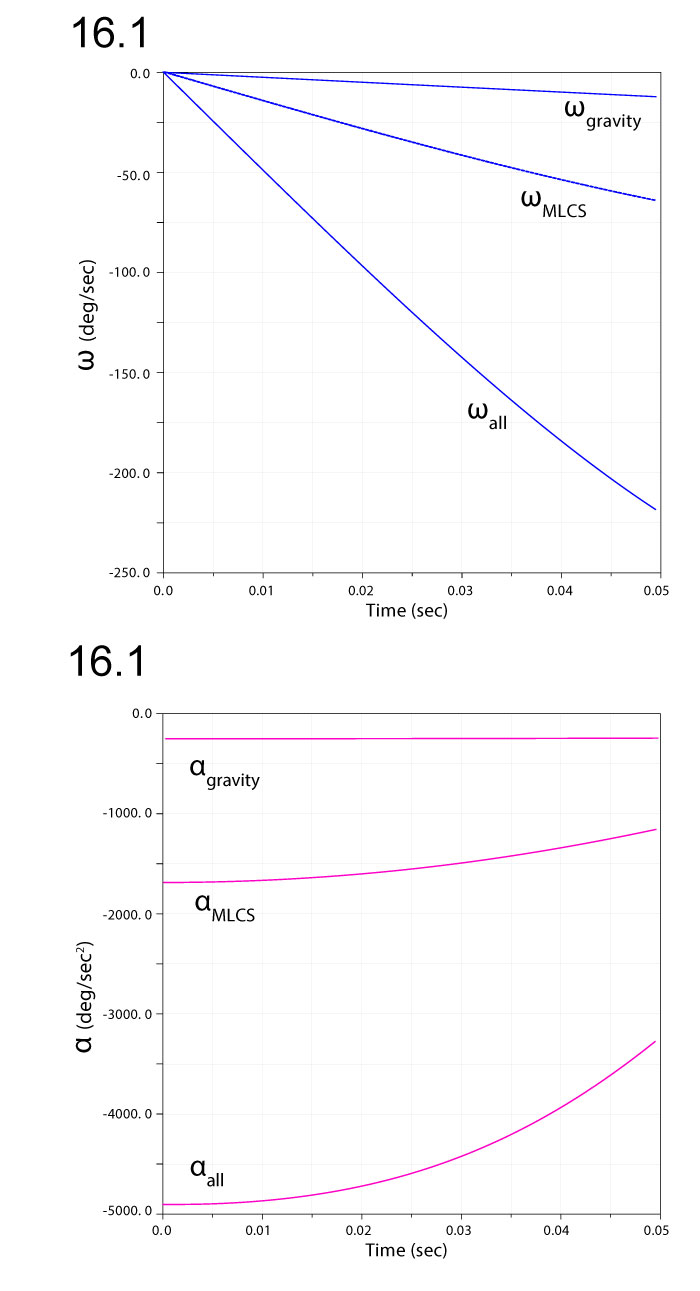
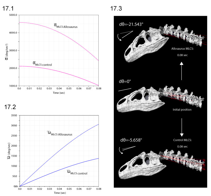
FIGURE 17. Comparison of ventroflexive angular accelerations (1), velocities (2), and displacements dθ (3), for two different reconstructions of m. longissimus capitis superficialis (MLCS). Absolute values of and ω enable comparisons of relative magnitudes. The ventral insertion of the muscle in of Allosaurus imparts over twice the (and torque) of the control throughout the 0.08 sec of the simulation (1), and reaches 3.8 times the angular displacement (3).