

 The challenge of hard-to-reach spaces in mechanical fossil preparation: Development of the Wada air scribe, a novel short-bodied air scribe with an adjustable handle
Article number: 27.1.a16
https://doi.org/10.26879/1296
Copyright Society for Vertebrate Paleontology, February 2024
Author biographies
Plain-language and multi-lingual abstracts
PDF version
Submission: 24 April 2023. Acceptance: 25 January 2024.
ABSTRACT
Pneumatic air scribes are essential tools for mechanical fossil preparation, particularly in vertebrate fossils. Fossil preparators need to choose the sizes and power of the air scribe depending on the volume and hardness of rock matrix and fossil specimens. However, traditional air scribes, characterized by their long, straight, pen-shaped shafts (typically 100-150 mm in length) and fixed heads, poses challenges in narrow and hard-to-reach spaces, such as intricate bone surfaces and deep cavities within fossils. Moreover, when preparing microvertebrate fossils, the limited working space for long air scribes between the microscope’s objective lens and the fossil specimen hinders effective preparation. To overcome these challenges, we have developed the Wada air scribe, a novel short-bodied air scribe constructed from hardware readily available at home improvement stores. The new Wada air scribe has an exceptionally compact 35 mm body and the handle with a hinge, providing an adjustable working angle for ergonomic and versatile use. Despite its short body, performance of the newly developed Wada air scribe is comparable to conventional air scribes with a similar stylus size. In addition, the Wada air scribe can upcycle used styli that are too short to continue using in the conventional air scribe. Overall, the Wada air scribe offers an effective solution to the limitations of conventional air scribes, enhancing the capabilities of fossil preparators in their vital work.
Tomonori Tanaka. Institute of Natural and Environmental Sciences, University of Hyogo, and Museum of Nature and Human Activities, Yayoigaoka 6, Sanda, Hyogo, Japan. tanaka@hitohaku.jp
Kazumi Wada. Museum of Nature and Human Activities, Yayoigaoka 6, Sanda, Hyogo, Japan. kwada@hitohaku.jp
Akiko Shinya. Field Museum of Natural History, 1400 S. DuSable Lake Shore Dr., Chicago, Illinois 60605, USA. ashinya@fieldmuseum.org
Tadahiro Ikeda, Institute of Natural and Environmental Sciences, University of Hyogo, and Museum of Nature and Human Activities, Yayoigaoka 6, Sanda, Hyogo, Japan. tikeda@hitohaku.jp
Keywords: pneumatic air scribe; palaeontological methods; laboratory techniques; micropreparation
Final citation: Tanaka, Tomonori, Wada, Kazumi, Shinya, Akiko, and Ikeda, Tadahiro. 2024. The challenge of hard-to-reach spaces in mechanical fossil preparation: Development of the Wada air scribe, a novel short-bodied air scribe with an adjustable handle. Palaeontologia Electronica, 27(1):a16.
https://doi.org/10.26879/1296
palaeo-electronica.org/content/2024/5151-wada-air-scribe
Copyright: February 2024 Society of Vertebrate Paleontology.
This is an open access article distributed under the terms of the Creative Commons Attribution License, which permits unrestricted use, distribution, and reproduction in any medium, provided the original author and source are credited.
creativecommons.org/licenses/by/4.0
INTRODUCTION
Fossil preparation is essential to palaeontological research as it transforms rocks into scientific specimens (Brown, 2013). While the basic preparation techniques for fossil vertebrates were established in early 1900s (Riggs, 1903; Bather, 1908; Hermann, 1908, 1909), new preparation techniques and tools have been developed over the last century (e.g., Whybrow, 1985; Brinkman, 2009; Wada et al., 2012; Brown, 2013; Brown and Holliday, 2021; Shinya et al., 2022). Much of the knowledge on fossil preparation, collection care, and fossil conservation methods is shared within palaeontological communities (Association of Materials & Methods in Palaeontology, 2023; Preparator Resources, 2023; The Paleontology Portal Fossil Preparation, 2023). However, local palaeontological laboratories and museums sometimes independently develop specific preparation methods and techniques to address regional challenges posed by unique geology, depositional conditions, preservation biases and the complex morphology of the fossils themselves. These refined techniques are often limited to in-house use and are rarely shared with the broader palaeontological community.
One of the most important innovations in the field of fossil preparation was the development of the pneumatic hammer, which served as the prototype of today’s pneumatic air scribes (Riggs, 1903; Brinkman, 2009). Pneumatic air scribes, resembling pen-shaped hand-held jackhammers operated using compressed air, were originally developed as industrial engraving tools (Ratkevich, 1998). The pneumatic air scribe, known for its power, efficiently removes a substantial volume of consolidated matrix from the fossil specimen. Palaeontologist Elmer S. Riggs of Chicago’s Field Museum of Natural History introduced this innovative preparation tool in 1903 (Riggs, 1903), and its use rapidly spread among American palaeontologists (Brinkman, 2009). Over the past 120 years, numerous technicians have improved its design and performance while retaining the basic pen-shape. Today, well-established manufactures such as USA-based Chicago Pneumatic® and PaleoTools ®, as well as European-based HW tools and Zoic®, provide air scribes of variable sizes (100-150 mm in length) and power levels to suit the needs of various palaeontological laboratories and museums worldwide (e.g., Chicago Pneumatic, 2023; PaleoTools, 2023; Zoic, 2023). Air scribes are now regarded as the workhorse of mechanical preparation.
Commercially available pneumatic air scribes have been used for fossil preparation in the Museum of Nature and Human Activities Hyogo (MNHAH), Japan. This is because vertebrate fossils from Hyogo prefecture, southwestern Japan, are often preserved in well consolidated mudstone, and manual preparation techniques using a pin vise fitted with a tungsten carbide needle have been proven ineffective. Even a nearly complete three-dimensionally preserved articulated Mesozoic frog skeleton, with a snout-vent length is less than 30 mm, had to be prepared with air scribes because chemical preparation methods (Rutzky et al., 1994) could not be applied due to the risk of damaging vulnerable micro-vertebrate elements. Additionally, three-dimensional (3D) images obtained from non-destructive method such as computed tomography (CT) were insufficient to examine its morphology in detail (Ikeda et al., 2016).
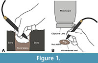 In MNHAH dinosaur lab, mechanical preparation methods using air scribes were often the only choice for preparing both macro-vertebrate fossils including sauropod and hadrosaurid dinosaurs and anthracotheriid mammals (Tsubamoto et al., 2007; Saegusa and Ikeda, 2014; Kobayashi et al., 2021) and micro-vertebrate fossils including frogs, lizards, eggshells, and small mammals (Ikeda and Saegusa, 2013; Kusuhashi et al., 2013; Ikeda et al., 2015; Ikeda et al., 2016; Tanaka et al., 2016; Tanaka et al., 2020; Ikeda et al., 2022). Using commercially available air scribes however, preparators were often required to hold them at awkward angles when removing matrix from hard-to-reach spaces in highly complex and fragile fossils, such as the intricate surfaces of pneumatic bones and inside deep cavities (e.g., sauropod vertebrae) (Figure 1A). Even the smallest available air scribes (e.g., Micro Jack 1 by PaleoTools®) sometimes become stuck between the objective lens of the microscope and the fossil (Figure 1B), making it nearly impossible to use them effectively. The addition of an auxiliary lens, such as a Barlow lens, to the objective lens can extend the working distance between the objective lens and the specimen (Cavigelli, 2009), but this extension comes at the expense of reduce magnification, necessitating the use of eyepieces with higher magnification to compensate. It is important to note that not all microscope setups can accommodate a Barlow lens and high-magnification eyepieces. Even when such configuration is possible, the reduction in magnification can adversely affect image quality, particularly making finer details appear less crisp and distinct compared to using only a high-magnification objective lens.
To address these disadvantages encountered with conventional long-bodied air scribes, we developed an extremely short-bodied air scribe with a handle that can adjust the angle of impact using hardware readily available at home improvement stores. We named it the Wada air scribe, in honor of the principal developer Kazumi Wada. The first prototype was made in the MNHAH dinosaur lab in 2014 (see Figure S1 in Appendix 1). Subsequent rigorous testing and refinements led to the completion of the current model of the Wada air scribe in 2015. The Wada air scribe represents an innovative fossil preparation tool, highly modifies the basic pen-shaped form and enhances the performance of the conventional air scribe. In this article, we describe how to build the Wada air scribe so that fossil preparators in other laboratories can replicate and add it to their preparation toolkit.
HEALTH AND SAFETY
To make Wada air scribe described herein requires in parts to perform metal forging. It is important to ensure the health and safety protocol to prevent accidents. The metal forging, which involves the shaping and reshaping of metal using extreme heat and pressure, rigorous safety measures are crucial to mitigate potential hazards. One must be equipped with proper personal protective equipment (PPE) such as heat-resistant clothing, gloves, safety goggles, and helmets to shield them from high temperatures, flying sparks, and molten metal splatters. Comprehensive training programs should also be taken to learn about the safe operation of forging machinery, the proper handling of hot materials, and emergency procedures. Furthermore, well-maintained and regularly inspected equipment is essential to reduce the risk of malfunction, as any lapses in maintenance could lead to dangerous situations. Safety protocols should also be in place within metal forging areas. Adequate ventilation systems should be in place to minimize exposure to harmful fumes and dust, while fire prevention measures, such as properly placed extinguishers and fire-resistant barriers, must be readily available.
MATERIALS AND METHODS
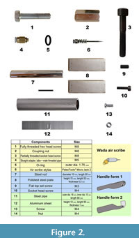 The hardware components used to build the air scribe and handles can be found at affordable prices in home improvement stores. Components were selected based on processability, compatibility, and strength. General tools including a 100 mm disc grinder (e.g., Makita 9533B), drill taps, punches, a bench vise, and a hammer were used to process all metal (e.g., cutting, shaping, drilling, and pressing). To build the Wada air scribe, six components are required: one fully threaded hex head screw with thread size M8, one coupling nut with thread size M8, one partially threaded socket head screw with high tensile strength steel with thread size M8, one straight adapter with tube × male threaded pipe with thread size M5, one O-ring with outer diameter 1.75 mm, and one set of air scribe stylus with a spring and an O-ring (Figure 2). A shortened stylus from Micro Jack 2 by PaleoTools® can be used for this design.
Because of the exceptionally compact design of the Wada air scribe's short body, prolonged usage of this tool on its own can lead to hand cramps and strain. To mitigate the risk of potential health issues, we have also designed handles. We propose two unique handle design options, offering preparators the flexibility to choose the one that best suits their abilities of metal working and aligns with their laboratory setup. Each handle requires four components as shown in Figure 2. The components used for the handle form 1 were as follows: one steel rod of 10 mm by 65 mm, two polished steel plates of 15 mm by 50 mm by 4.5 mm, one flat top set screw with thread size M3, and one socket head screw with thread size M4. The components used for the handle form 2 were as follows: one steel pipe of 80 mm in length with outer diameter 16 mm and inner diameter 13 mm, one aluminum sheet of 50 mm by 13mm by 1 mm, one screw with thread size M4, and one nut with thread size M4.
The design drawings and production workflow of the Wada air scribe, handle form1, handle form 2, and the coupling of the air scribe with a handle are described herein and figured in Figure 3, Figure 4, Figure 5, Figure 6, Figure 7, and Figure 8 respectively. In addition, Appendix 2, Appendix 3, Appendix 4, Appendix 5, Appendix 6, Appendix 7, Appendix 8, Appendix 9, Appendix 10 (available in one zipped download) contain 3D images of the Wada air scribe, the Wada air scribe with handle form 1 and 2, as well as detailed component of the Wada air scribe and handles. The scan images of the Wada air scribe and its components/handles were acquired utilizing a Nikon XT H225 ST and subsequently rendered into 3D images at the Tomakomai Industrial Technology Center in Tomakomai City, Hokkaido, Japan. Using a 3D printer could facilitate the creation of the handle, provided the chosen material is capable of withstanding rigorous use. However, we advise against 3D printing the Wada air scribe because it needs to endure compressed air, and the printed part may not meet the required safety standards and pressure specifications.
Wada air scribe
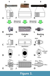 The Wada air scribe is composed of three parts: junction (Figure 3A-E), cylinder (Figure 3F-J), and bushing (Figure 3K-O). The measurements of each processed component are shown in the schematic drawings in Figure 3D, E, I, J, N, O. Each part of the Wada air scribe was constructed by the following workflows. Further detail production is found in Figure S2, Figure S3, Figure S4 in Appendix 1.
Junction. To create a junction, one-fifth of a screw head of a fully threaded hex head screw (Figure 3A) was removed. The hexagonal head was ground into a cylindrical shape before being cut diagonally at an angle of approximately 70 degrees from the horizontal plane (Figure 3B, C). Additionally, a shallow groove was created at the base of the head to accommodate an O-ring (Figure 3C). A tapped hole with an M5 thread size was then made on the diagonally cut surface (Figure 3D, E). On the opposite side of the hex head, a 1 mm diameter hole was drilled towards this tapped hole, then reduced the opening to 0.5 mm to create an orifice, which aids in increasing the air pressure (Figure 3E). This was achieved with a small hammer and a nail (see step 5 of Figure S2 in Appendix 1). Finally, the surface with the orifice was polished using sandpapers ranging from #400 to #2000 grit. The 3D image of the junction can be found in Appendix 2.
Cylinder. A cylinder was created from a coupling nut. First, the lateral surface of the coupling nut was ground into a cylindrical shape (Figure 3F, G). Subsequently, the left and right lateral sides were chamfered in preparation for attaching a handle at a later stage. The distance between the left and right surfaces was approximately 10 mm (Figure 3I). Additionally, a small 3 mm diameter depression was made in the center of the right side of the surface (Figure 3G, H). This depression accommodates a flat top set screw (component 9 in Figure 2), which serves as the pivot point for adjusting the air scribe body angle. The 3D image of the cylinder can be found in Appendix 3.
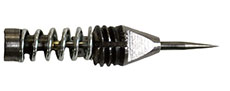
 Bushing. A bushing was made from the mid-section of a socket head screw with high tensile strength steel (thread size M8) (Figure 3K-O). First, non-threaded side was tapered into a conical shape and a 1.6 mm guide hole for a stylus was drilled in the center of the bushing as shown in Figure 3O. The threaded side was ground to form a 5 mm long, 4 mm diameter cylinder (Figure 3L, M, O) to create a stem that a spring can fit over (Figure 4). The opposing sides of the bushing's tip were chamfered to facilitate easy attachment or detachment using a pair or pliers or a wrench (Figure 3L, M). A groove for exhaust was added to one side of the bushing’s thread (Figure 3N). Finally, the processed bushing underwent a quenching procedure for hardening. This involved exposing the bushing to controlled heating with a gas burner in a darkened room until it reached a vibrant red color. Subsequently, the heated bushing was immediately immersed in machine oil for several seconds. The 3D image of the bushing can be found in Appendix 4.
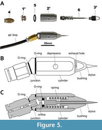 Assemblage of the three parts. An assembly of the Wada air scribe is shown in Figure 5. A straight adapter of a tube × male threaded pipe was screwed into the junction, ensuring an airtight connection with the use of an appropriately sized O-ring in between. Next, an air-line was connected to the straight adapter. Before connecting it to the cylinder, an additional O-ring was inserted at the base of the threaded side of the junction. To complete the assembly, a stylus with an O-ring and a spring was inserted through the guide hole in the bushing, and the bushing was attached to the cylinder using a pair of pliers or a wrench. The 3D image of the Wada air scribe can be found in Appendix 5.
Handle Form 1
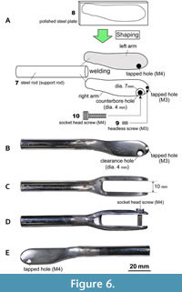 For this workflow, the welding process is an essential step that cannot be omitted. An alternative non-welded handle making process is described in the Handle Form 2. The handle form 1 is composed of three parts: a support rod and two arms (Figure 6). The handle form 1 was constructed using the following workflow: Two elliptically shaped steel plates were cut to create the left and right arms. The outer-facing lateral surfaces were ground for improved grip, and these arms were then welded to the supporting rod (Figure 6A). On the left arm, a tapped hole with an M4 thread size was drilled (Figure 6A). On the right arm, a counterbore hole with a 4 mm cylindrical hole that widens to a 7 mm coaxial hole for the socket head screw was drilled (Figure 6A, B). To secure the Wada air scribe between them, a socket head screw with an M4 thread size (component 10 in Figure 2) was inserted through these holes (Figure 6D). It functioned as a locking screw when fastening the left and right arms together. An additional tapped hole with an M3 thread size was drilled into the right arm (Figure 6A, E). This hole served as a pivot point for adjusting the angle of the air scribe body when attaching the handle to the Wada air scribe. The space between the left and right arms was set approximately 10 mm, matching the width of the air scribe body (Figure 6C). The 3D image of the handle form 1 can be found in Appendix 6.
Handle Form 2
 The handle form 2 is composed of two parts: the support rod (Figure 7C-F) and a body holder (Figure 7G, H). Each part of the handle form 2 was constructed by the following workflows.
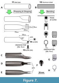
Support rod. One end of the steel pipe (component 11 in Figure 2), a length of 20 mm, was compressed using a bench vise and a hammer, reducing the compressed section to 22 mm by 6 mm (Figure 7A). The compressed end of the steel pipe was shaped to match the configuration shown in Figure 7A and then polished to a smooth finish. A notch measuring 4 mm in width and 15 mm in length was carefully cut at the bottom tip to create the body holder arms. A 4 mm clearance hole was subsequently drilled at the very end of these body holder arms. The 3D image of the support rod can be found in Appendix 7.
Body Holder.
The aluminum sheet was bent along the contour of the Wada air scribe body using a bench vise and a hammer, as depicted in Figure 7B. Additionally, a 4 mm clearance hole was drilled into the lower section of the body holder. The 3D image of the body holder can be found in Appendix 8.
Coupling the Wada air scribe with a handle
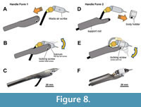 With Handle Form 1. The Wada air scribe was securely fastened between the left and right arms of the handle using the flat top set screw, as shown in Figure 8A and B. The air scribe’s angle could be finely adjusted and then locked in place, ranging from 0° (Figure 9A) to approximately 90° (Figure 9B) in relation to the handle. This adjusted angle could be secured by tightening a socket head screw. To minimize the vibration impact from the tool on the hand, the handle was covered with a closed-cell polyurethane foam sleeve with a 16 mm inner diameter (Figure 9C). The 3D image of the Wada air scribe with handle form 1 can be found in Appendix 9.
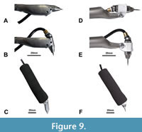 With Handle Form 2. The Wada air scribe was inserted in the body holder and the air-line was carefully guided through the support rod, as shown in Figure 8D. Subsequently, the lower part of the body holder was positioned between the left and right arms of the support rod (Figure 8E) and firmly secured with a screw and nut. Same as in the handle form 1, the air scribe’s angle with this handle form 2 could also be finely adjusted, ranging from 0 ° (Figure 9D) to approximately 90° (Figure 9E) in relation to the support rod, and the chosen angle could be secured by tightening a screw and nut. This handle was also covered with a foam padding to reduce the vibration impact on the hand (Figure 9F). The 3D image of the Wada air scribe with handle form 2 can be found in Appendix 10.
DISCUSSION
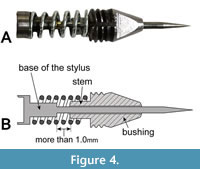
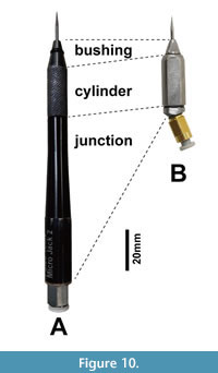 The Wada air scribe was originally designed by Kazumi Wada, former Chief Preparator at the MNHAH Dinosaur Lab, to overcome the limitations of the commercially available air scribes, which typically had a pen-shaped, long-body with a fixed angle. The fundamental modification to the traditional air scribe arose from the realization that the body length of a conventional air scribe (Figure 10A) was not the determining factor for its performance. In 2014, a prototype was created (see Figure S1 in Appendix 1), and it posed several challenges in achieving a balance between shortening the air scribe and maintaining optimal performance. One of the biggest challenges was to determine the ideal length of the bushing (Figure 4). While the bushing provides stability to the stylus, a longer bushing would contradict our goal of minimizing the air scribe’s length. To achieve a compact design, a portion of the bushing was ground to fit inside a spring, effectively extending the bushing (referred to as the stem in Figure 3M, Figure 4B). To ensure the air scribe operated optimally, a guide hole had to be at least 12 mm in length when using a stylus with a 1.6 mm diameter, and the base of the stylus and the stem of the bushing had to avoid contact (Figure 4B). Furthermore, it was discovered that the distance between the base of the stylus and the stem need to be greater than 1 mm, equivalent to the amplitude of the spring during a single stylus stroke. To meet these criteria, the stem’s length was adjusted to 5 mm and its width to 4 mm, resulting in a total bushing length of 15 mm (Figure 3O). As a result, the overall length of the Wada air scribe was successfully reduced to 35 mm, making it the shortest air scribe known for use in the palaeontological laboratories to date. This design is cost-effective, requiring only five components readily available in the home-improvement stores. Despite its significantly short body, the Wada air scribe performs on par with conventional long-bodied air scribes with a similar stylus size.
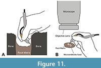 Additional challenges included making the air scribe ergonomic to hold and allowing for adjustable impact angle. Given its compact 35 mm length, the Wada air scribe could be challenging for preparators to hold comfortably for extended period. This issue was resolved by introducing a holder, and the innovation came in the form of a hinged holder, which enable the user to secure the air scribe angles ranging from 0° to 90° relative the holder (Figure 8, Figure 9). This feature allowed users to hold the Wada air scribe in an ergonomic position, especially when working in the hard-to-reach spaces (Figure 11A).
The novel configuration of the short-bodied Wada air scribe with an attached handle with an adjustable angled tip also greatly enhanced the productivity in micropreparation (Figure 11B). Micropreparation of small fossils demands precise control of the tool under a microscope to avoid inadvertent damage (Madsen, 1996). The Wada air scribe proved highly effective in this regard, preventing it from getting stuck between the objective lens of the microscope and the fossil specimen due to its extremely short body and adjustable impact angle (Figure 11B).
Finally, the Wada air scribe can upcycle styli from the Micro Jack (PaleoTools ®) that are too short to continue using in existing products. It can fit styli as short as 25 mm, thereby maximizing their utility and reducing waste in a palaeontological laboratory.
CONCLUSION
In this article, we provide herein comprehensive, step-by-step instructions for constructing the short-bodied Wada air scribe, making it accessible for fossil preparators worldwide. While specialized preparation tools to overcome regional palaeontological challenges, such as the Wada air scribe, are frequently developed by local laboratories and museum, their distribution remains limited. We believe that actively disseminating and demonstrating in-house palaeontological tools and methods can significantly advance fossil preparation techniques and strengthen palaeontological research.
The Wada air scribe was initially designed and ingeniously crafted using readily available nuts and bolts from a home improvement store in 2014. Its primary purpose was to address challenges encountered in mechanical fossil preparation, especially in hard-to-reach spaces. By the end of 2014, the MNHAH dinosaur lab successfully integrated three Wada air scribe units into its daily workflow, and additional nine units were assembled by 2019. Over time, we have continually refined its design and the Wada air scribes have become the primary mechanical preparation tools in the MNHAH. After nearly a decade, all Wada air scribes continue to function seamlessly, demonstrating their robustness and sustained operational reliability.
Overall length of the Wada air scribe is 35 mm, making it the smallest air scribe known for use in palaeontological labs. While it can be used as is, we also designed an ergonomic handle with a hinge to reduce hand strain and fatigue. Additionally, the Wada air scribe can recycle used styli that are too short for use in commercially available air scribes. Despite its small size, the performance matches that of other air scribes with similar-sized styli. Its exceptional maneuverability in confined spaces effectively overcomes the limitations associated with long-bodied air scribes.
ACKNOWLEDGEMENTS
We greatly thank Dr Masaya Iijima (Nagoya University) for his critical review, comments and suggestions during the initial/early stages of this paper. Shigehiro Kato (Museum of Nature and Human Activities, Hyogo) provided a proposal for the nomenclature of the novel air scribe, the Wada air scribe, described in this article. We also thank fossil preparators Chitose Ohta, Maho Nishio, Tomomi Ikeda, Yukako Yamaguchi, Miki Fukui, Sumio Shimizu (the MNHAH Dinosaur Lab), and Akihiko Okugishi (the Hall of Ancient Life of Tambasasayama City) for assisting in the development and improvement of the Wada air scribe. In addition, we express our gratitude to Junya Morimoto, a technician at the Tomakomai Industrial Technology Center, for his assistance in acquiring CT scanning data and rendering 3D models. Finally, we extend our sincere appreciation to two anonymous reviewers for their meticulous review and invaluable critical feedback and suggestions.
REFERENCES
Association of Materials & Methods in Palaeontology. 2023. Association of Materials & Methods in Palaeontology. Retrieved April 21, 2023.
https://paleomethods.org/
Bather, F.A. 1908. The preparation and preservation of fossils, p. 76–90. Handbook of paleontological techniques. Museum Journal, London.
Brinkman, P. 2009. Modernizing American fossil preparation at the turn of the 20th century, p. 21–34. In Brown, M.A., Kane, J. F., and Parker W. G. (eds.), Methods in Fossil Preparation: Proceedings of the First Annual Fossil Preparation and Collections Symposium.
Brown, M.A. 2013. The development of “modern” palaeontological laboratory methods: a century of progress. Earth and Environmental Science Transactions of the Royal Society of Edinburgh, 103:205–216.
https://doi.org/10.1017/S1755691013000352
Brown, M.A. and Holliday, C.M. 2021. Non-traditional applications of fire in fossil preparation. Palaeontologia Electronica, 24:a22.
https://doi.org/10.26879/1149
Cavigelli, J.P. 2009. Micropreparation... one sand grain at a time, p. 41–52. In Brown, M.A., Kane, J.F., and Parker, W.G. (eds.), Methods in Fossil Preparation: Proceedings of the First Annual Fossil Preparation and Collections Symposium.
Chicago Pneumatic. 2023. Chicago Pneumatic®. Retrieved April 21, 2023.
https://compressors.cp.com/
Eberth, D.A., Shannon, M., and Noland, B.G. 2007. A bonebeds database: classification, biases, and patterns of occurrence, p. 103–220. In Eberth, D.A., Rogers, R.R., and Fiorillo, A.R. (eds.), Bonebeds: Genesis, Analysis, and Paleobiological Significance.
Hermann, A. 1908. Modern Methods of Excavating, Preparing and Mounting Fossil Skeletons. The American Naturalist, 42:43–47.
https://doi.org/10.1086/278898
Hermann, A. 1909. Modern laboratory methods in vertebrate paleontology. Bulletin of the American Museum of Natural History, 26:283–331.
Ikeda, T., Ota, H., and Matsui, M. 2016. New fossil anurans from the Lower Cretaceous Sasayama Group of Hyogo Prefecture, Western Honshu, Japan. Cretaceous Research, 61:108–123.
https://doi.org/10.1016/j.cretres.2015.12.024
Ikeda, T., Ota, H., and Saegusa, H. 2015. A new fossil lizard from the Lower Cretaceous Sasayama Group of Hyogo Prefecture, western Honshu, Japan. Journal of Vertebrate Paleontology, 35:e885032.
https://doi.org/10.1080/02724634.2014.885032
Ikeda, T., Ota, H., Tanaka, T., Ikuno, K., Kubota, K., Tanaka, K., and Saegusa, H. 2022. A fossil Monstersauria (Squamata: Anguimorpha) from the Lower Cretaceous Ohyamashimo Formation of the Sasayama Group in Tamba City, Hyogo Prefecture, Japan. Cretaceous Research, 130:105063. https://doi.org/10.1016/j.cretres.2021.105063
Ikeda, T., and Saegusa, H. 2013. Scinocomorphan lizards from the Lower Cretaceous Sasayama Group, Hyogo, Japan. Journal of Fossil Research, 4:2–14.
Kobayashi, Y., Takasaki, R., Kubota, K., and Fiorillo, A.R. 2021. A new basal hadrosaurid (Dinosauria: Ornithischia) from the latest Cretaceous Kita-ama Formation in Japan implies the origin of hadrosaurids. Scientific Reports, 11:8547.
https://doi.org/10.1038/s41598-021-87719-5
Kusuhashi, N., Tsutsumi, Y., Saegusa, H., Horie, K., Ikeda, T., Yokoyama, K., and Shiraishi, K. 2013. A new Early Cretaceous eutherian mammal from the Sasayama Group, Hyogo, Japan. Proceedings of the Royal Society B: Biological Sciences, 280:20130142.
https://doi.org/10.1098/rspb.2013.0142
Madsen, S.K. 1996. Some techniques and procedures for microvertebrate preparation, p. 25–36. In Cifelli, R.L. (ed.), Techniques for recovery and preparation of microvertebrate fossils. Oklahoma Geological Survey Special Publication.
PaleoTools. 2023. PaleoTools®. Retrieved April 21, 2023.
https://www.paleotools.com/
Preparators Resources. 2023. Society of Vertebrate Paleontology. Retrieved April 21, 2023.
https://vertpaleo.org/preparators-resources-2/
Ratkevich, R. 1998. Air tool preparation of fossils. Rocks & Minerals, 73:418–422.
https://doi.org/10.1080/00357529809603083
Riggs, E.S. 1903. The use of pneumatic tools in the preparation of fossils. Science, 17:747–749.
https://doi.org/10.1126/science.17.436.747
Rutzky, I.S., Elvers, W.B., Maisey, J.G., and Kellner, W.A. 1994. Chemical preparation techniques, p. 155–186. Vertebrate Paleontological Techniques. Cambridge University Press, Cambridge, UK.
Saegusa, H., and Ikeda, T. 2014. A new titanosauriform sauropod (Dinosauria: Saurischia) from the Lower Cretaceous of Hyogo, Japan. Zootaxa, 3848:1–66.
https://doi.org/10.11646/zootaxa.3848.1.1
Shinya, A., Van Beek, C., and Makovicky, P. 2022. Plaster field jackets using air filter media: an alternative to traditional burlap and plaster jackets, p. 304. 82nd Annual Meeting of the Society of Vertebrate Paleontology: Program and Abstracts.
Tanaka, K., Zelenitsky, D.K., Saegusa, H., Ikeda, T., DeBuhr, C.L., and Therrien, F. 2016. Dinosaur eggshell assemblage from Japan reveals unknown diversity of small theropods. Cretaceous Research, 57:350–363.
https://doi.org/10.1016/j.cretres.2015.06.002
Tanaka, K., Zelenitsky, D.K., Therrien, F., Ikeda, T., Kubota, K., Saegusa, H., Tanaka, T., and Ikuno, K. 2020. Exceptionally small theropod eggs from the Lower Cretaceous Ohyamashimo Formation of Tamba, Hyogo Prefecture, Japan. Cretaceous Research, 114:104519.
https://doi.org/ 10.1016/j.cretres.2020.104519
The Paleontology Portal Fossil Preparation. 2023. American Museum of Natural History. Retrieved April 21, 2023.
http://preparation.paleo.amnh.org/
Tsubamoto, T., Matsubara, T., Tanaka, S., and Saegusa, H. 2007. Geological age of the Yokawa Formation of the Kobe Group (Japan) on the basis of terrestrial mammalian fossils. Island Arc, 16:479–492.
https://doi.org/10.1111/j.1440-1738.2007.00577.x
Wada, K, Ikeda, T, Saegusa, H, and Shinya A. 2012. Stylus sharpening instrument for fossil preparation, p. 119-120. 72th Annual Meeting of the Society of Vertebrate Paleontology: Program and Abstracts.
Whybrow, P.J. 1985. A History of Fossil Collecting and Preparation Techniques. Curator: The Museum Journal, 28:5–26.
https://doi.org/10.1111/j.2151-6952.1985.tb01686.x
Zoic. 2023. Zoic®. Retrieved August 21, 2023.
https://www.zoicpalaeotech.co.uk/
