

FIGURE 1. UUIC 1873, slab of Nugget Sandstone bearing multiple trackways. 1, the slab as it is exhibited in the halls of the Frederick Albert Sutton Building of the University of Utah in Salt Lake City. 2, image of the slab rotated 150o clockwise to show the trackways in their original orientation. Scale bars equal 10 cm.
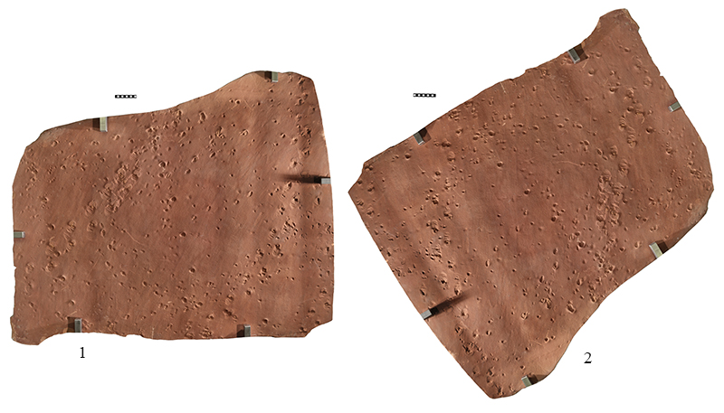
FIGURE 2. High resolution image of UUIC 1873. Scale bar equals 10 cm.
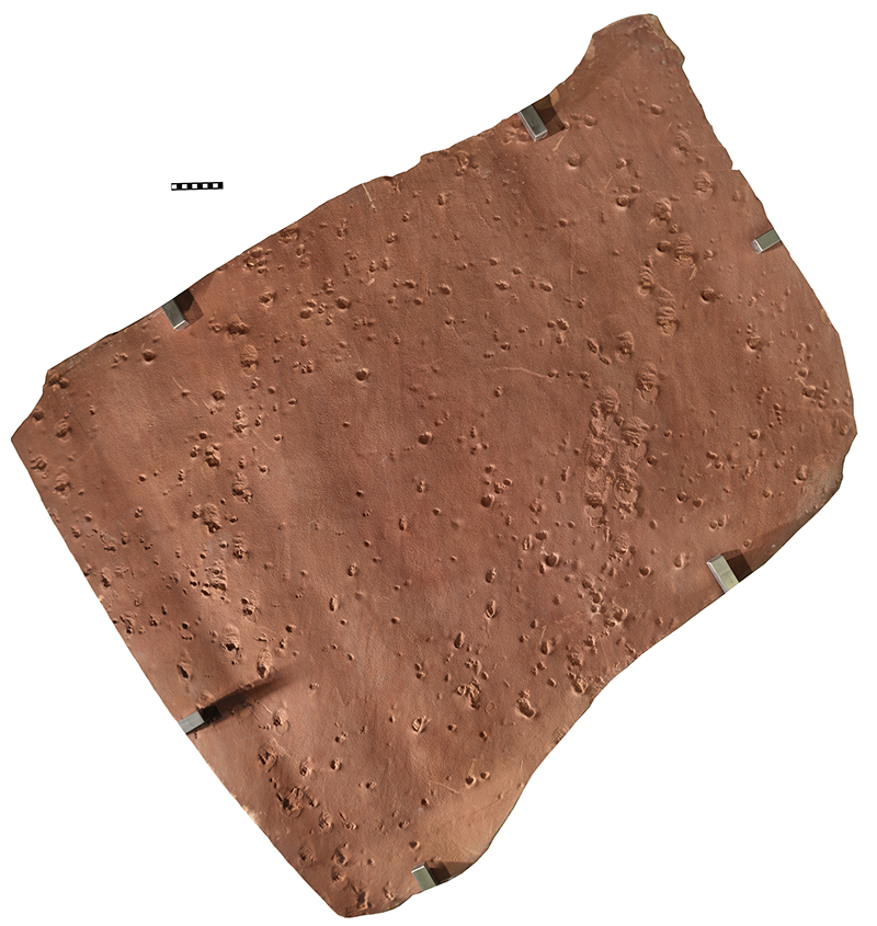
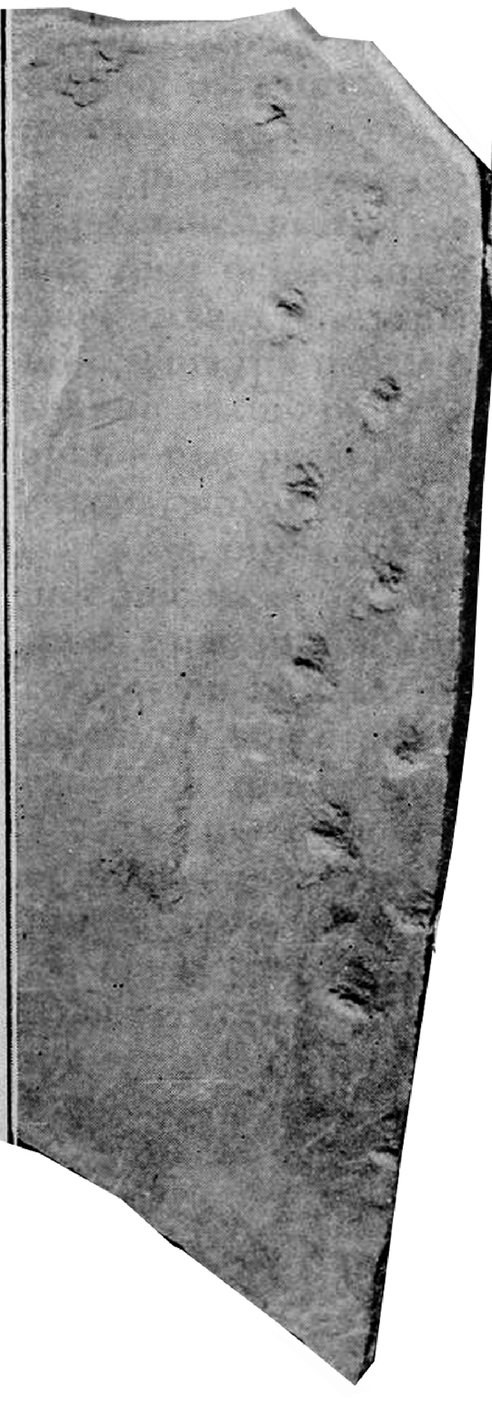
FIGURE 3. Map of tracks and trackways on UUIC 1873. Scale bar equals 10 cm.
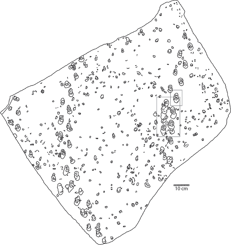
FIGURE 4. Distant and near views of locality DNM 490. 1, site as approached from the southeast. Arrow points to track bearing surface. 2, the track surface of 490 is the large bedding plane surface on the erosional remnant of Nugget Sandstone.
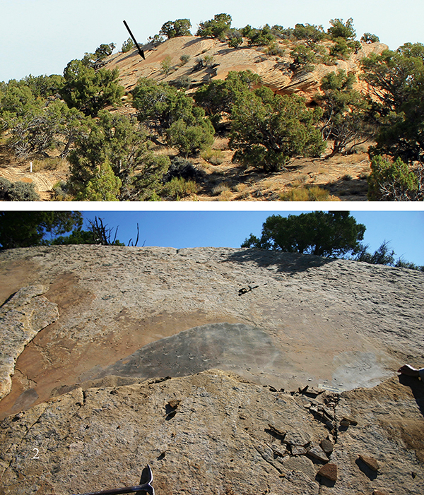
FIGURE 5. Composite photograph of the track-bearing surface of DNM 490. The crests of wind ripples are evident, especially near the center of the image, and provide a good indication of the primary dip direction of the slope of the dune. Scale bars equal 10 cm. Center scale bar distorted by photo stitching process.
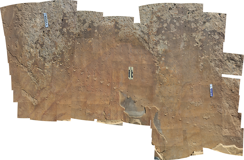
FIGURE 6. Map of 490, based on composite photo in Figure 5. Scale bar equals 10 cm in 5 cm increments.
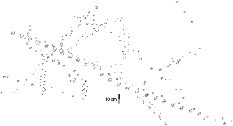
FIGURE 7. Composite image of the long transverse trackway at DNM 490 presented in 3 parts and the entire trackway. In each case, the trackway is oriented so that left (west) end is to top of page and upslope is to right of page. 1, left (west) end of the trackway. 2, section of the trackway adjacent to and to the right (east) of the section in Figure 7.1. 3, section of the trackway adjacent to and to the right (east) of the section in Figure 7.2. 4, the entire composite image of the trackway. Scale bars equal 10 cm.
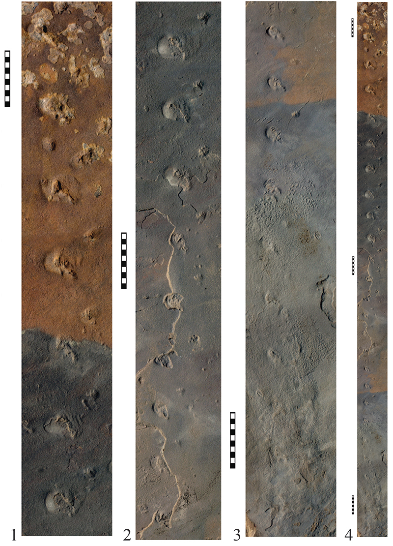
FIGURE 8. Transverse trackway from locality 490, in sections. These are enlargements of sections of the composite photo in Figure 7. Sections do not overlap, but do abut one another. 1, left side of trackway (cf. with Figure 6) is the top section. 2, the next section in the trackway, adjacent to and to the right of Figure 8.1. 3, the next section in the trackway, adjacent to and to the right of Figure 8.2. Scale bars equal 5 cm.
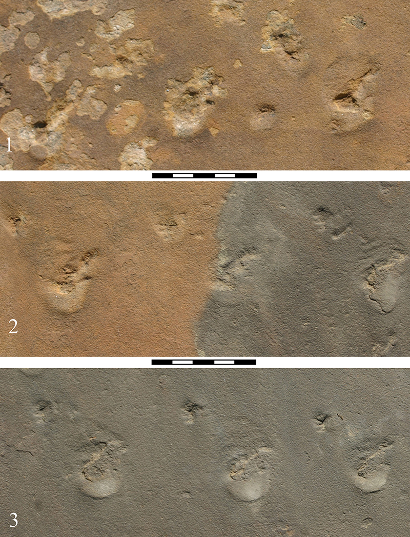
FIGURE 9. Transverse trackway from locality 490, in sections. These are enlargements of sections of the composite photo in Figure 7. Sections do not overlap, but do abut one another. 1, the next section in the trackway, adjacent to and to the right of Figure 8.3. 2, the next section in the trackway, adjacent to and to the right of Figure 9.1. 3, the next section in the trackway, adjacent to and to the right of Figure 9.2. Scale bars equal 5 cm.
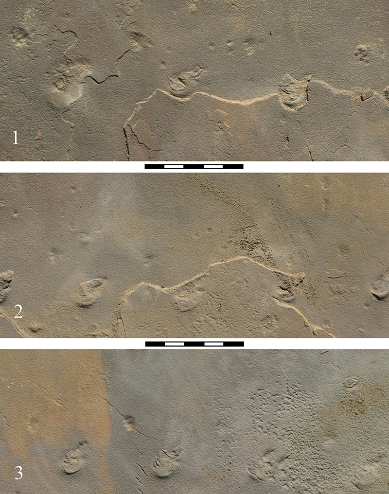
FIGURE 10. Transverse trackway from locality 490, in sections. These are enlargements of sections of the composite photo in Figure 7. Sections do not overlap, but do abut one another. 1, the next section in the trackway, adjacent to, and to the right of Figure 9.3. 2, the next section in the trackway, adjacent to and to the right of Figure 10.1. Scale bar equals 5 cm.
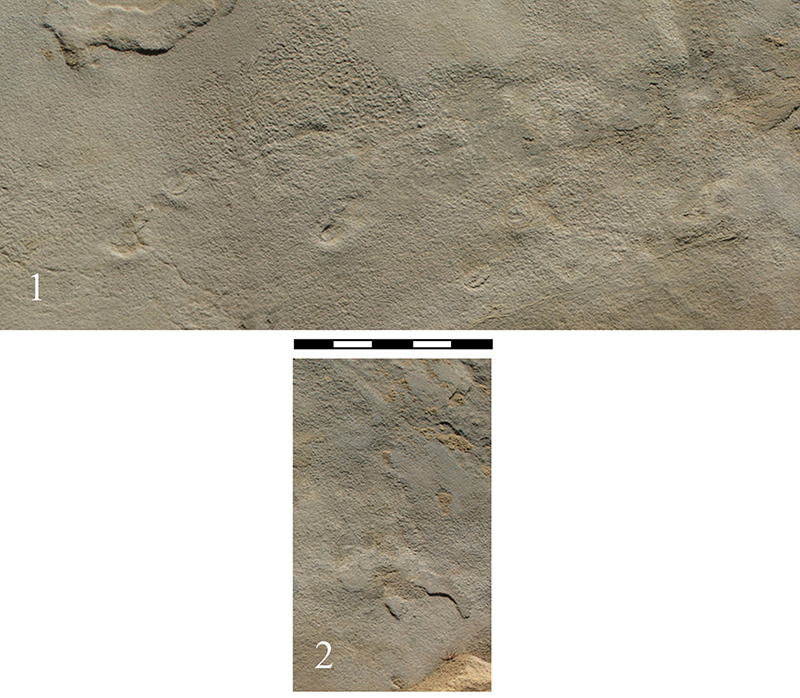
FIGURE 11. Detail of a track from the downslope trackway along the right side of UUIC 1873. The location of this figure is indicated by the small rectangle in Figure 3. Note the anterior platform, the posterior, slumped depression, and the small space for the foot filled with lighter colored sand.
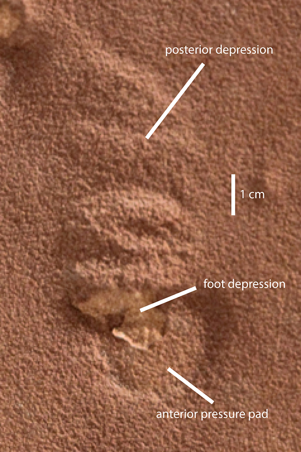
FIGURE 12. Segment of the trackway along the right side of UUIC 1873 that shows closely spaced tracks. The location of this figure is indicated by the large rectangle in Figure 3. Note also the impressions of digits on two of the tracks and the smaller anterior platforms of the manus tracks immediately anterior to the pes tracks.
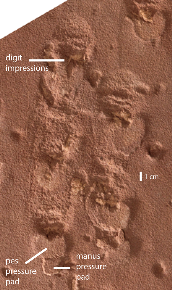
FIGURE 13. Reproduction of part of the photograph from Buss (1921). The original figure has been cropped to show only the Brasilichnium trackway and rotated 180o to show the tracks in what we interpret to be their original vertical orientation. No scale in photo, but based on Buss’ description, the block is slightly less than 1 m.

 Poster Winners 2024
 The Princeton Field Guide to Mesozoic Sea Reptiles