DISCUSSION
Information about a track’s surface morphology needs to be collected and
distributed as objectively as possible because these raw data form the
foundation of ichnological analysis. Interpretive drawings should be made to
highlight aspects of interest, but such representations are most effective when
presented in conjunction with less subjective records of the original material. The need for accurate documentation is particularly intense for specimens that
remain in the field beyond easy access by other workers. Anaglyphs have the
potential to record and transmit a track’s morphology with high fidelity.
Anaglyphs are by no means perfect. Special glasses are required to view
relatively large color image files. Another concern is variation in color
output, which can lead to ghosting artifacts when a gel does not completely
filter out the image meant for the opposite eye. Low quality glasses can
significantly darken an anaglyph, which already suffers from loss of saturation
and true color balance. Finally, new methods are needed to standardize camera
positioning in the field. Our hand-held technique is fast and flexible, but
intraocular distances vary and image pairs frequently require minor rotation,
translation, and rescaling in order to align. Despite these drawbacks,
anaglyphs hold promise for efficiently maximizing the amount of data that might
be extracted by faithfully recording a track’s 3-D geometry.
Alternative Imaging Formats
Relative to anaglyphs, most other formats entail additional subjectivity,
information loss, or optical illusion. For example, simple outline drawings are
the most commonly used method of portraying the general size, shape, and
placement of tracks in published studies. Although silhouettes can be generated
quickly and cheaply, they are notoriously subjective because a continuous
surface must be reduced to a single edge (e.g.,
Thulborn 1990). More
importantly, information about depth and texture is excluded (e.g.,
Moratalla et
al. 1997). Internal and external track features are sometimes represented by
additional lines, stippling, and shading (e.g.,
Hitchcock 1858;
Currie et al.
1991;
Farlow and Chapman 1997), but artistic bias remains a concern (Baird 1952;
Thulborn 1990).
Isoheight contour maps (Lim et al. 1989;
Farlow and Lockley 1993;
Graham et al.
1996;
Farlow and Chapman 1997;
Rasskin-Gutman et al. 1997) and moiré topography
(Ishigaki and Fujisaki 1989) record internal shape information, but at a
relatively low resolution. Neither takes advantage of the shading or cast
shadow mechanisms of spatial perception. True depth must be represented
numerically, because the absolute inter-contour spacing is not apparent from the
lines themselves. Nor is either method easily amenable to specimens in the
field, although scanning of in situ surfaces is likely to become viable in the
near future. Computer renderings of tracks as distorted wire-mesh grids (Farlow
and Chapman 1997; Rasskin-Gutman et al. 1997) provide more complete depth
information, but must be viewed from an oblique perspective, which hides some
features and hinders comparison among tracks. Other workers have used stipple
density or tones of gray to depict relative depth (Harris
et al. 1996; Gatesy et al.
1999; Gatesy 2001),
but such illustrations have never been executed with any quantitative control.
Photography would appear to offer the simplest and most objective solution to
illustrating footprints, but snapshots can fall short as well (Figure 1,
Figure 3,
Figure 4, and
Figure 6). As discussed earlier, conditions in the field are often unsuitable for
faithfully capturing a track’s shape. A surface may be indiscernible in the
ambient illumination provided by the bright haze of fog, gray overcast of
clouds, or permanent shade under an overhang. Under clear skies the contrast
may be too high, obscuring details in both the brightest and darkest areas. Waiting for better weather or shooting at a different time of day is not always
possible. More commonly, the sun is simply too high, too low, or at an
unfavorable direction to produce ideal shading and shadows, which can cause
these cues to be confusing or incomplete.
 In monocular photographs, directional illumination can create misleading shading
cues that cause depth reversal. Although images of whole tracks can be affected
(Figure 3), the dimple-like skin impressions of theropod dinosaurs, in
particular, are strikingly similar to the spheres used by
Ramachandran (1988) to
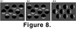
explore this phenomenon of human perception. For example,
Figure 8.1 is a
computer rendering of nine shaded spheres. The four lit from above are
perceived as convex “pimples” rising out of the page, whereas the five lit from
below are seen as concave “dimples” (Ramachandran 1988). The viewer-dependent
nature of this illusion can be demonstrated by rotating
Figure 8.1 by 180
degrees, as in Figure 8.2. Spheres previously perceived as convex are now seen
as concave, and vice versa. Spheres lit from the side remain ambiguous (Figure
8.3). Our brain is accustomed to seeing objects lit from above by a single
light source (Ramachandran 1988;
Palmer 1999;
Ware 2004), so we subconsciously
expect a photograph of a track to follow this pattern. Since tracks are
traditionally presented vertically as if walking up the page, lighting from an
anterior direction fits our implicit assumption, and we can frequently, if not
always, interpret the shape correctly from shading and shadows. Photographs of
tracks lit from their posterior aspect appear to be illuminated from a source at
the bottom of the page, which can cause confusion (Figure 4.4). Orienting all
photographs to a consistent lighting direction could alleviate this visual
conflict, but would clearly hamper morphological comparison among tracks. A
reference object such as a small cube helps document the position of the light
source but may not remove the flipping artifact.
In monocular photographs, directional illumination can create misleading shading
cues that cause depth reversal. Although images of whole tracks can be affected
(Figure 3), the dimple-like skin impressions of theropod dinosaurs, in
particular, are strikingly similar to the spheres used by
Ramachandran (1988) to
explore this phenomenon of human perception. For example,
Figure 8.1 is a
computer rendering of nine shaded spheres. The four lit from above are
perceived as convex “pimples” rising out of the page, whereas the five lit from
below are seen as concave “dimples” (Ramachandran 1988). The viewer-dependent
nature of this illusion can be demonstrated by rotating
Figure 8.1 by 180
degrees, as in Figure 8.2. Spheres previously perceived as convex are now seen
as concave, and vice versa. Spheres lit from the side remain ambiguous (Figure
8.3). Our brain is accustomed to seeing objects lit from above by a single
light source (Ramachandran 1988;
Palmer 1999;
Ware 2004), so we subconsciously
expect a photograph of a track to follow this pattern. Since tracks are
traditionally presented vertically as if walking up the page, lighting from an
anterior direction fits our implicit assumption, and we can frequently, if not
always, interpret the shape correctly from shading and shadows. Photographs of
tracks lit from their posterior aspect appear to be illuminated from a source at
the bottom of the page, which can cause confusion (Figure 4.4). Orienting all
photographs to a consistent lighting direction could alleviate this visual
conflict, but would clearly hamper morphological comparison among tracks. A
reference object such as a small cube helps document the position of the light
source but may not remove the flipping artifact.
When merged as stereopairs, many of the shortcomings of monocular photographs,
including lighting from below, can be overcome. Information from binocular
disparity ensures that a viewer will perceive the correct surface orientation. In the same way, an anaglyph can make the most of two photographs taken under
less than ideal conditions by combining them into a stereoscopic whole greater
than the sum of its parts.
