METHODS
In the following sections the procedures leading
to animations in stereo vision at improved depth of focus are described in three
steps:
- depth of focus enhancement (Fusing method),
- construction of stereo images, and
- construction of virtual reality objects.
Fusing Method: Generation of Images with Extended
Depth of Focus in Mono-Vision:
 Reduced
depth of field is a physical limitation in light optical microscopes. With the
help of computer-aided microscopy this difficulty can be circumvented by
separating out the sharp regions in a stack of digital images from several focal
planes and then re-combining them to a composite with extended depth of focus.
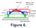
In practice these focal levels are not planes but are rather 'focal volumes'
with the heights being equal to the depth of focus (e.g., Fig.
6.1). Any surface that intersects this volume appears as a sharp image. The
depth of focus,
Reduced
depth of field is a physical limitation in light optical microscopes. With the
help of computer-aided microscopy this difficulty can be circumvented by
separating out the sharp regions in a stack of digital images from several focal
planes and then re-combining them to a composite with extended depth of focus.
In practice these focal levels are not planes but are rather 'focal volumes'
with the heights being equal to the depth of focus (e.g., Fig.
6.1). Any surface that intersects this volume appears as a sharp image. The
depth of focus,  ,
is an inverse function of the magnification or the numerical aperture of the
lens system (Shillaber 1944).
At high magnifications or at high numerical apertures,
is small and at low magnifications or low numerical apertures,
is large. When the focal volume is idealized to a focal plane, the image content
from the focal volume can be considered as the integral of gray-level variation
across the depth of focus per pixel.
,
is an inverse function of the magnification or the numerical aperture of the
lens system (Shillaber 1944).
At high magnifications or at high numerical apertures,
is small and at low magnifications or low numerical apertures,
is large. When the focal volume is idealized to a focal plane, the image content
from the focal volume can be considered as the integral of gray-level variation
across the depth of focus per pixel.
Considering focal planes in this simplified
manner, the sharp areas in a focal plane can be identified by calculating the
local sharpness, which is the variability of gray levels in a selected subregion
of a digital image (variance of gray levels or the difference between maximum
and minimum gray levels in a region of interest). In order to detect a sharp
region by gray-level variation color or shading effects in the original image
must first be removed, which is done by generation of a gradient image (for
example with a Sobel convolution filter). The sharp region appears then as an
area with a high frequency of gray-level variation, while a blurred or unsharp
region displays low variability in gray levels.
These principles are implemented in the NIH-Image
macro 'Focus Extend', which was applied in this study. Images were acquired by
moving the microscope body to a 'mono-mode' (= coaxial) position and taking
gray-level images at three different focal levels (Figure
6.2-6.4). The three images were then fused into a single composite with
extended focus (Fig. 6.5). The matching
of images must be precise enough for image fusion otherwise edge effects will
occur. Image alignment for each level was performed by identification of a small
landmark, that remains visible throughout the entire stack. Using NIH-Image,
Adobe Photoshop, or any other image processing software, the images from the
individual focal planes can be aligned in horizontal (x) or vertical (y)
directions until the landmark has identical coordinates in all levels.
