PREPARATION OF STEREO-PAIR IMAGES
 As
described above, stereo-vision is obtained when two images of the same object
are produced from slightly different angles of view, shaded with different
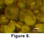
colors, and then superposed. This was accomplished here by first producing a
stereo-pair of gray-level images of the object at the same focal plane with NIH-Image.
For this purpose the microscope was set to the "stereo-vision"
position for taking the right image, and then moved sidewards to the left, to
shoot the left image (Fig. 7). An
anaglyph image was then produced using a graphics program capable of displaying
color information in several channels (e.g., Adobe Photoshop, ImageJ). The left
gray-level image was inserted into the red channel and the right gray-level
image was inserted into the green channel of a new RGB-mode document, while the
blue channel was changed to black. When recombining all channels (Fig.
8) the stereo-effect can be observed with red-green anaglyph glasses.
As
described above, stereo-vision is obtained when two images of the same object
are produced from slightly different angles of view, shaded with different
colors, and then superposed. This was accomplished here by first producing a
stereo-pair of gray-level images of the object at the same focal plane with NIH-Image.
For this purpose the microscope was set to the "stereo-vision"
position for taking the right image, and then moved sidewards to the left, to
shoot the left image (Fig. 7). An
anaglyph image was then produced using a graphics program capable of displaying
color information in several channels (e.g., Adobe Photoshop, ImageJ). The left
gray-level image was inserted into the red channel and the right gray-level
image was inserted into the green channel of a new RGB-mode document, while the
blue channel was changed to black. When recombining all channels (Fig.
8) the stereo-effect can be observed with red-green anaglyph glasses.
 Stereo
Vision with Correction for Depth of Focus
Stereo
Vision with Correction for Depth of Focus
Improved stereographic vision for a microscopic
object is obtained if the depth of focus enhancement is done in the left and
right images of a stereo-pair. This was realized by first obtaining
stereo-images at several, pair-wise identical focal planes across the object. In
a second step the NIH-Image macro ExtendFocus was applied to each of the left
and right stack. Finally, the pair of fused images was combined into a single
anaglyph for stereo-vision.
Because of the different geometry of the light
paths in monoscopic mode (= left) and stereoscopic mode (= right) position of
the magnification changer body, two separate fusion procedures must be applied
for the left and right images. In the monoscopic mode (left side), images taken
from different focal planes need no or only little correction for the best
overlap because the geometry of the light path through the microscope is
coaxial. In the stereoscopic mode (= right side) position, images from the
individual focal planes do not match because of the oblique light beam with
respect to the optical axis of the microscope (see above). 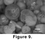 The
offset of identical points (Dx) between different focal planes must be
eliminated prior to the application of the focus extend macro. This was
accomplished by selecting one of the images as a reference and shifting the
remaining images by a constant amount until all images overlap completely. The
correction can be accomplished either by manual determination of the offset
using the x,y coordinates of a selected structure on the object that can
be easily identified at all focal levels, or by calculation of the offset as a
function of z using Equation (2). After alignment of the right images,
the left and the right image stacks can be fused with the Focus Extend macro.
The result is a pair of stereo images at improved depth of focus, from which an
anaglyph for stereo vision can be generated (see Stereo-Vision
without Correction for Depth of Focus). Figure
9 illustrates these steps for the same example as shown in Figure
6, Figure 7, and Figure
8.
The
offset of identical points (Dx) between different focal planes must be
eliminated prior to the application of the focus extend macro. This was
accomplished by selecting one of the images as a reference and shifting the
remaining images by a constant amount until all images overlap completely. The
correction can be accomplished either by manual determination of the offset
using the x,y coordinates of a selected structure on the object that can
be easily identified at all focal levels, or by calculation of the offset as a
function of z using Equation (2). After alignment of the right images,
the left and the right image stacks can be fused with the Focus Extend macro.
The result is a pair of stereo images at improved depth of focus, from which an
anaglyph for stereo vision can be generated (see Stereo-Vision
without Correction for Depth of Focus). Figure
9 illustrates these steps for the same example as shown in Figure
6, Figure 7, and Figure
8.
Animated Sequences
Movie sequences were created with Quick-Time
Virtual Reality Authoring Studio from a series of fused mono- and stereo images
at stepwise varying angular positions of the specimen. 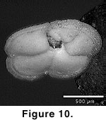 Specimen
orientation was performed with a universal eucentric stage, that was constructed
for this purpose. The stage is small enough that it fits under the microscope
and allows the user to tilt and rotate the specimen at equal intervals while the
object remains in focus (i.e., without operating the focus control of the
microscope). Focus-corrected images for mono- and stereo images were prepared
for tilt intervals of 10° over an angular range of 270°. Within this range,
the foraminifer can be watched from its spiral-, keel-, and umbilical sides
without re-mounting the specimen. In the present example the individual images
were resized at 400 x 400 pixels in order to minimize the size of the final VR
file (for better performance when embedding it into a html document).
Specimen
orientation was performed with a universal eucentric stage, that was constructed
for this purpose. The stage is small enough that it fits under the microscope
and allows the user to tilt and rotate the specimen at equal intervals while the
object remains in focus (i.e., without operating the focus control of the
microscope). Focus-corrected images for mono- and stereo images were prepared
for tilt intervals of 10° over an angular range of 270°. Within this range,
the foraminifer can be watched from its spiral-, keel-, and umbilical sides
without re-mounting the specimen. In the present example the individual images
were resized at 400 x 400 pixels in order to minimize the size of the final VR
file (for better performance when embedding it into a html document). 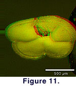 In
order to arrive at a precession-free movement, all images were aligned a second
time with respect to a previously defined reference point on the shell.
Determination of the necessary corrections in x and y directions
was done with NIH-Image (for monoscopic vision) or ImageJ (for stereoscopic
vision), and the image alignment was accomplished using Adobe Photoshop. Figure
10 and Figure 11 show Quick-Time VR
representations of the specimen in monoscopic and stereoscopic vision.
In
order to arrive at a precession-free movement, all images were aligned a second
time with respect to a previously defined reference point on the shell.
Determination of the necessary corrections in x and y directions
was done with NIH-Image (for monoscopic vision) or ImageJ (for stereoscopic
vision), and the image alignment was accomplished using Adobe Photoshop. Figure
10 and Figure 11 show Quick-Time VR
representations of the specimen in monoscopic and stereoscopic vision.
Discussion and Conclusions
The described method is a powerful and inexpensive
tool for generating close-range animated 3D stereo representations of
microfossils next to existing visualization techniques for small objects. While
previous methods of this type were derived from SEM images at full focal
resolution, the present method was explicitly developed for use with light
microscopy and limited depth of focus. Alternative techniques, such as SEM or
X-ray computer tomography may lead to superior results, but these sophisticated
technologies are expensive to acquire and maintain. Serial sectioning techniques
for surface reconstruction purposes, as described by Sutton
et al. 2001, represents another possibility, but is restricted currently to
particle-size ranges of centimeters to a few millimeters. The methods presented
are still labour-intensive, but have potential for standard application if the
individual steps can be automated and if the precision of the mechanical
orientation control can be improved. The technique is especially suitable for
the illustration of microfossil type specimens in 3D on the internet, in
illustrated microfossil databases, in digital taxonomic atlases (e.g., for usage
onboard research ships), for demonstration and teaching purposes, or to show the
beauty of microfossils in public displays or museum exhibitions.
