| |
GENERAL OUTLINE OF MECHANICAL DIGITIZING METHODS
Prerequisites
As digital representations of fossil bones will usually lack many features of the real specimen, such as surface rugosities and textures or discolorations indicative of breaks and deformation, maximum care must be given to the process of selecting specimens for digitizing. Especially those with deformations of the bone obvious on the real specimen but invisible on a digital representation must be avoided.
There are two possible aims when digitizing:
a) digitally constructing 'ideal', that is undeformed and complete bones from several partial or damaged specimen, or
b) digitizing individual specimens exactly, e.g., to obtain a digital representation of one complete animal.
For (a), as an absolute minimum, a specimen must either allow measuring of at least two characteristic dimensions and their relation to each other (preferably total length and proximal or distal width) or three distinctive landmarks that can be pinpointed with millimeter accuracy. Additionally, the specimen must possess a significant section of non-deformed and non-eroded bone surface to be digitized in correct relation to said characteristic dimension. For example, a complete articular end that has been shifted in relation to the long axis of the bone through compression is useless, as the exact orientation cannot be ascertained. Only if the correct three dimensional relations of the characteristic dimension and the area digitized can be ascertained, can several pieces be combined correctly. These requirements are far less strict than those commonly used for other studies (e.g.,
Wilhite 2003b), as the methods described here allow combining sections from several specimens to obtain artificial 'ideal' digital bones.
Regarding (b), any specimen can be used. However, for most applications using digital data, especially scientific study, it is advisable to use well-preserved material. In case of elements that exist as left and right copies, it is often better to mirror contralateral elements, than to use a badly preserved bone. Similarly, in elements with a bilateral symmetry, mirroring one well-preserved half may be better than using a badly damaged part, as long as the symmetry plane is obvious on the bone. Such data operations must, however, be clearly mentioned, best as a text entry in the digital file itself. Also, it is important to remember that damage obvious on a real bone will usually not be easily visible on the digital file. Because digital files can be (and often are) widely shared between researchers worldwide, it is important to select well-preserved and typical examples. Otherwise, there
is a risk that imperfect or unusual specimens will be accidentally treated as complete or normal.
General Overview of the Digitizing Procedure
Here, only a short description of the general process is given. Various versions
of the basic procedure have different advantages and limitations, and are best
suited for various kinds of fossils, as detailed in
Appendix A and
Appendix B. Step-by-step directions
for program and digitizer use are given in
Appendix C,
Appendix D, and
Appendix E.
 For digitizing we used Immersion™ Microscribe 3D digitizers. A Microscribe consists of a base plate, on which a four part arm is mounted. The base plate contains sockets for cables connecting the Microscribe to a PC. The position of the arm's tip is measured through the displacement of the joints between the various parts compared to the 'neutral' position, into which the machine must be put before it is switched on. By pressing a button on a foot pedal, the operator can determine when data on the tip's location is transferred to the computer. Various commercially available Computer Aided Design (CAD) softwares can receive this data and transfer it into data points. We only used Rhinoceros®, which has the additional ability to automatically interpolate NURBS curves between the data points delivered by the digitizer.
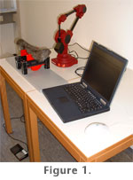
Figure 1 shows a typical setup of the digitizer and laptop along with a specimen (Diplodocus sp. GPIT ?160). It is possible to digitize large objects while sitting on the floor (Wilhite 2003b), often made necessary by the large weight and resulting immobility of specimens such as sauropod longbones. Working on a table as shown in
Figure 1 is decidedly more comfortable and reduces worker fatigue, as it is much easier to work the foot pedal in this position. While this seems trivial, we found that prolonged digitizing in an uncomfortable position increases the likelihood of time-consuming errors significantly, and also increases the time required for digitizing specimens. The quality of the digitized data also decreases when the operator assumes an uncomfortable working position such as squatting on the floor. At worst, this can lead to cramps or jittering of the hand, making data acquisition impossible. For digitizing we used Immersion™ Microscribe 3D digitizers. A Microscribe consists of a base plate, on which a four part arm is mounted. The base plate contains sockets for cables connecting the Microscribe to a PC. The position of the arm's tip is measured through the displacement of the joints between the various parts compared to the 'neutral' position, into which the machine must be put before it is switched on. By pressing a button on a foot pedal, the operator can determine when data on the tip's location is transferred to the computer. Various commercially available Computer Aided Design (CAD) softwares can receive this data and transfer it into data points. We only used Rhinoceros®, which has the additional ability to automatically interpolate NURBS curves between the data points delivered by the digitizer.
Figure 1 shows a typical setup of the digitizer and laptop along with a specimen (Diplodocus sp. GPIT ?160). It is possible to digitize large objects while sitting on the floor (Wilhite 2003b), often made necessary by the large weight and resulting immobility of specimens such as sauropod longbones. Working on a table as shown in
Figure 1 is decidedly more comfortable and reduces worker fatigue, as it is much easier to work the foot pedal in this position. While this seems trivial, we found that prolonged digitizing in an uncomfortable position increases the likelihood of time-consuming errors significantly, and also increases the time required for digitizing specimens. The quality of the digitized data also decreases when the operator assumes an uncomfortable working position such as squatting on the floor. At worst, this can lead to cramps or jittering of the hand, making data acquisition impossible.
Preparation of specimens: Some markings must be made on the specimens before digitizing can take place. We placed masking tapes of different manufacture on them, on which we drew the required markings with felt tip pens. Although we never caused any damage to specimens this way, it is theoretically possible that the masking tape damages the bone surface. Thus, curatorial personnel should always be involved in the decision what tape to use, and where and how to apply it. Extremely delicate specimens should therefore be marked as little as possible. We recommend removing any tape from the bones as soon as possible.
If it is impossible to put masking tape on a specimen, digitizing it with point clouds or NURBS curves is still possible. Point clouds that partly overlap can be aligned manually in Rhinoceros® after digitizing. However, recalibration is impossible, unless there are at least three distinct and very small landmarks on the bone that can be used instead of markings. Not being able to recalibrate the digitizer creates a large risk of errors in the final file. Also, digitizing may take more time, and more erroneous curves may be created, if the bone cannot be marked in places difficult to digitize. NURBS digitizing without markings on the bone requires making a mental mark of curve starts and paths, to avoid drawing curves that intersect, leave large gaps, or otherwise results in errors in the final digital surface. This is possible even for large specimens, but requires extreme concentration, which increases worker fatigue. Additionally, the likelihood of erroneous curves increases, requiring additional time for correction both during digitizing and editing. We have successfully tested digitizing a sauropod metacarpal without markings.
Data acquisition: The easiest way to obtain 3D data of large bones with the Microscribe is by storing curves, not points, as detailed by
Wilhite (2003b). Both curves and surfaces in Rhinoceros® are created as NURBS object. NURBS stands for non-uniform rational B-spline. Constructing a surface is easy when using a loft function on curves, which creates a NURBS surface. Even more comfortable is lofting a 'closed loft', leading directly to a closed 3D body, which is the method used most extensively here. Point clouds cannot be surfaced without much effort in Rhinoceros 3.0®. The current version Rhinoceros 4.0® allows meshing point clouds directly, but the process is error-prone and less accurate than in Geomagic®.
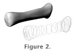 The process of digitizing with NURBS curves is best described as the electronic equivalent of wrapping sub-parallel wires around the bone, then pulling a cloth tight around the wires. See
Figure 2 for an example of a digital bone (left radius of Dicraeosaurus sattleri MB.R.2622) and the curves used to create it. The curves are obtained by entering a simple command into Rhinoceros®, placing the tip of the digitizer on the bone at the start point of the intended curve, pressing down the foot pedal, and moving the digitizer tip over the bone until the desired end point of the curve is reached. Then, the foot pedal must be released. Neighboring curves must be of similar length and should be roughly parallel. Large differences in length or separation tend to produce artifacts in the final surface. Also, curves may not cross each other. The process of digitizing with NURBS curves is best described as the electronic equivalent of wrapping sub-parallel wires around the bone, then pulling a cloth tight around the wires. See
Figure 2 for an example of a digital bone (left radius of Dicraeosaurus sattleri MB.R.2622) and the curves used to create it. The curves are obtained by entering a simple command into Rhinoceros®, placing the tip of the digitizer on the bone at the start point of the intended curve, pressing down the foot pedal, and moving the digitizer tip over the bone until the desired end point of the curve is reached. Then, the foot pedal must be released. Neighboring curves must be of similar length and should be roughly parallel. Large differences in length or separation tend to produce artifacts in the final surface. Also, curves may not cross each other.
Curves are placed at intervals at the operators' discretion and should be closely spaced where the morphology of the bone exhibits important features or where the topology changes abruptly, e.g., near cristae or at the articular ends. Relatively simple surface areas like shafts of longbones or scapular blades require few curves. The operator's judgment on the placement is one of the key elements that determine the accuracy of the digital bone.
If a bone cannot be represented by one set of sub-parallel curves due to its shape, it can be digitized by joining several partial surfaces or bodies together. Separate curve sets must be digitized for each part.
To reduce post-digitizing workload and achieve the most accurate results, closed curves reaching 360° around the bone are best. If a bone cannot be digitized with closed curves, due to its size or a fixed mounting that makes reaching all around it impossible, partial curves can be drawn and joined into closed curves.
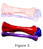 Alternatively, a point cloud can be collected with the digitizer.
Figure 3 shows point clouds of the lower left hind limb of the mounted Dicraeosaurus from the MFN (unnumbered) and the 3D files created from them. Point cloud digitizing is a method usually more time consuming than digitizing curves, as the full surface of the bone must be densely sampled. On the other hand, hardly any planning ahead is required, and there is no need to mark the bone extensively, saving time especially when a complex geometry renders curve-planning difficult. It is best used for small bones of complex shapes, or for rough representations of large bones at low resolution. Alternatively, a point cloud can be collected with the digitizer.
Figure 3 shows point clouds of the lower left hind limb of the mounted Dicraeosaurus from the MFN (unnumbered) and the 3D files created from them. Point cloud digitizing is a method usually more time consuming than digitizing curves, as the full surface of the bone must be densely sampled. On the other hand, hardly any planning ahead is required, and there is no need to mark the bone extensively, saving time especially when a complex geometry renders curve-planning difficult. It is best used for small bones of complex shapes, or for rough representations of large bones at low resolution.
Surface creation: A surface is created from curves as a NURBS surface, a 'loft', through a single command. If, which is most advisable, the entire surface is to be created in one piece (from closed curves), two points are also needed, one at each end of the bone. This will result in a closed body (resembling a deformed balloon) instead of an open surface (resembling a deformed tube).
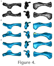 When digitizing point clouds, curves can be hand-built from suitable points, but this method is usually not advisable due to the high amount of work involved. Instead, current versions of Rhinoceros® can produce polygon meshes directly from point clouds. These usually require a few minutes' to half an hour's work of editing to remove artifacts and mesh errors, but this method allows accurate digitizing of small and complex shapes, such as small to mid-sized vertebrae.
Figure 4 shows the left humerus of GPIT 1 as a point cloud file, the resulting mesh in Geomagic®, and the final file produced by manual editing of the mesh. Both the initial meshing and all editing are, however, best accomplished in Geomagic®. When digitizing point clouds, curves can be hand-built from suitable points, but this method is usually not advisable due to the high amount of work involved. Instead, current versions of Rhinoceros® can produce polygon meshes directly from point clouds. These usually require a few minutes' to half an hour's work of editing to remove artifacts and mesh errors, but this method allows accurate digitizing of small and complex shapes, such as small to mid-sized vertebrae.
Figure 4 shows the left humerus of GPIT 1 as a point cloud file, the resulting mesh in Geomagic®, and the final file produced by manual editing of the mesh. Both the initial meshing and all editing are, however, best accomplished in Geomagic®.
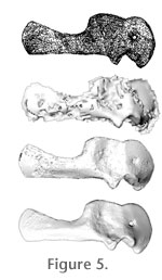 Unfortunately, when Rhinoceros® is used to create the mesh, the resulting 3D bodies are often smaller than the volume covered by the original point cloud, producing significant errors in the surface shape. Also, Rhinoceros® tends to produce more meshing errors near sharp bends in the surface geometry than the Geomagic programs suite (Figure 5). Additionally, as opposed to Geomagic®, Rhinoceros® does not offer an option to preserve the edges of meshes when reducing their polygon number. This results in 'digital erosion' of sharp edges. Digitizing bones via point clouds may require more effort than via curves, but is decidedly cheaper than CT or laser scanning. Unfortunately, when Rhinoceros® is used to create the mesh, the resulting 3D bodies are often smaller than the volume covered by the original point cloud, producing significant errors in the surface shape. Also, Rhinoceros® tends to produce more meshing errors near sharp bends in the surface geometry than the Geomagic programs suite (Figure 5). Additionally, as opposed to Geomagic®, Rhinoceros® does not offer an option to preserve the edges of meshes when reducing their polygon number. This results in 'digital erosion' of sharp edges. Digitizing bones via point clouds may require more effort than via curves, but is decidedly cheaper than CT or laser scanning.
Mobile fossil holder: Accuracy is paramount when digitizing fossils, as even slight aberrations of the digital curves can lead to significant shifts of volume or appearance. A slight unnoticed rotation of the specimen during digitizing may lead to a misinterpretation of range of movement of joints that include the articular ends of the bone. Mass estimates of complete animals may be off by significant amounts if bones of the pelvis girdle are misshaped or longbones gain or lose length or volume through errors during digitizing. More common than unnoticed errors are significant movements of the specimen due to unstable placement or physical contact. Especially small bones will shift at even the slightest touch while curves are being drawn, invalidating the last curve drawn and requiring time-consuming recalibration. A common method to avoid this is placing the specimen either in sandboxes, where they are often still prone to shifting and the sand is likely to get into the computer and digitizer, or to fix them with Play-Doh® or similar deformable substances. Since various chemicals damaging to fossil bone may leak from these materials, their use is problematic. Also, 360° reach around the fossil is not possible. A construction drawing of the holder is available on request.
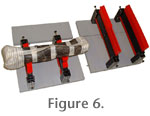 To solve these problems a variable holder was designed. It can be separated into small pieces and quickly reassembled.
Figure 6 shows the holder in the minimum configuration with an unnumbered GPIT Diplodocus metacarpal and the extension parts used for larger bones. This construction kit setup makes the holder easy to stow and transport. It consists of a base plate made from heavy polyurethane, custom made metal holders that can be placed at variable intervals on the base plate as desired, and commercially available plastic contour gauges supported by the metal holders. On these, the bones rest stably, are well supported, and resist shifting even when bumped. Using smoother plastic gauges instead of metal holders avoids the risk of scratching the bone. The base plate is split into four parts. These parts can be stuck together as needed in order to accommodate large bones, but are not cumbersomely large when used for small bones. The smallest possible assemblage, sufficient for objects up to the size of sauropod metatarsals or hadrosaur humeri (ca. 10x10x35 cm), weighs approximately 3 kg, the largest tested assemblage, sufficient even for sauropod pubes and radii, weighs about 8 kg. Theoretically, the holder can hold even larger bones, if a sufficient number of contour gauges are used to support the bones. To solve these problems a variable holder was designed. It can be separated into small pieces and quickly reassembled.
Figure 6 shows the holder in the minimum configuration with an unnumbered GPIT Diplodocus metacarpal and the extension parts used for larger bones. This construction kit setup makes the holder easy to stow and transport. It consists of a base plate made from heavy polyurethane, custom made metal holders that can be placed at variable intervals on the base plate as desired, and commercially available plastic contour gauges supported by the metal holders. On these, the bones rest stably, are well supported, and resist shifting even when bumped. Using smoother plastic gauges instead of metal holders avoids the risk of scratching the bone. The base plate is split into four parts. These parts can be stuck together as needed in order to accommodate large bones, but are not cumbersomely large when used for small bones. The smallest possible assemblage, sufficient for objects up to the size of sauropod metatarsals or hadrosaur humeri (ca. 10x10x35 cm), weighs approximately 3 kg, the largest tested assemblage, sufficient even for sauropod pubes and radii, weighs about 8 kg. Theoretically, the holder can hold even larger bones, if a sufficient number of contour gauges are used to support the bones.
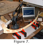 The fragility of the specimen strongly influences the ideal setup. More gauges mean better support, fewer gauges mean better access. The longest bone digitized during this project was a Brachylophosaurus rib from the JRDI. The excellent preservation and hardness of the bone allowed using only four gauges (Figure 7). On the other hand, the ribs of the Plateosaurus skeleton GPIT 1 could not be supported on the holder due to their fragility. Close enough spacing of the gauges would have made access to the lower side impossible. Curatorial personnel should always be included in the decision on what setup of the holder is employed. The fragility of the specimen strongly influences the ideal setup. More gauges mean better support, fewer gauges mean better access. The longest bone digitized during this project was a Brachylophosaurus rib from the JRDI. The excellent preservation and hardness of the bone allowed using only four gauges (Figure 7). On the other hand, the ribs of the Plateosaurus skeleton GPIT 1 could not be supported on the holder due to their fragility. Close enough spacing of the gauges would have made access to the lower side impossible. Curatorial personnel should always be included in the decision on what setup of the holder is employed.
Size range: The lower end of the size range of objects that can be digitized accurately is defined less by dimensions, but rather by the necessity to keep the object perfectly immobile without obscuring a large part of its surface. The smallest bones that we were able to digitize were less than 5 cm long, held in place on the table with two fingers, and digitized using point clouds. NURBS curve digitizing usually works well for objects with a length greater than 10 cm. Similarly, the maximum size is not defined by greatest (or least) extension, but rather by the complexity and size of the surface area. The larger and/or more complex in shape a bone is, the more recalibrations of the digitizer will be necessary to sample it sufficiently. For example, a 50 cm long sauropod vertebra may require more recalibrations than a 2 m long sauropod scapula. Each recalibration decreases the accuracy of any digitizing taking place after it. While in theory the size range is unlimited, our experience shows that recalibrating more than five times should be avoided. However, this number is not a hard limit, and there is no single bone in any extant or extinct vertebrate that is too large for the methods described here. Digitizing very large objects usually results in a reduced absolute, but not necessarily relative accuracy.
Manpower requirements: Normally, one person can transport the equipment and digitize bones alone. The digitizer and the fossil holder together fit into a standard suitcase, and weigh less than 20 kg. When digitizing very large bones it may be difficult for one person to operate both the digitizer arm and the foot pedal, especially if it is necessary to step around a mounted bone during digitizing. A second person should then be employed to operate the foot pedal. In this study, only a scapula of Giraffatitan (Brachiosaurus) brancai (MB.R.2912), mounted vertically, made a helper necessary.
Digitizing time requirements: The time needed for digitizing depends significantly on the expertise of the person operating the digitizer. Generally, between 5 and 20 minutes suffice to digitize a small or medium sized bone of simple geometry, such as a longbone, metatarsal, pelvic bone, or rib. Very large bones (over 1 m length) or complex shapes (vertebrae, skull elements) may take several hours, although usually 30 minutes are sufficient. Post-digitizing editing may require several hours. Normally, though, simple bone shapes will not require editing at all, while editing complex shapes can usually be completed within 15 minutes. Polygon meshes based on point cloud data are easier to edit in Geomagic®, which usually takes a few minutes only, than in Rhinoceros®, which may take up to half an hour. Overall, the techniques allow digitizing and final editing of virtual bones as fast as or even faster than extracting and editing virtual bones from CT data. Considering that CT scanning involves wrapping and transporting the specimens, plus time for the actual scanning, mechanical digitizing is decidedly faster.
|