FIGURE 1. Signal waveform (1) and wavelets with various frequencies placed in various locations along the waveform (2). The frequency and magnitude of the signal plotted in (1) changes with location in a constant manner.
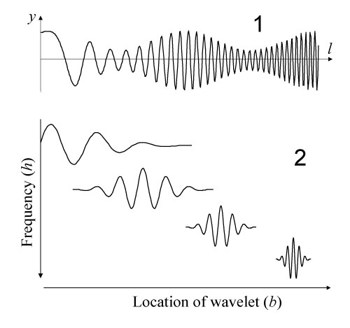
FIGURE 2. The Morlet wavelet used in the present study as a mother wavelet. The Morlet wavelet is a complex wavelet in which a pair of wavelets with different phases constitutes the real and imaginary components. The horizontal axis represents the relative position with respect to the center of the wavelet, and the vertical axis measures the magnitude of the wavelet.
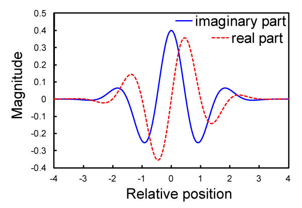
FIGURE 3. Contour plots of scalograms in the frequency (h = 2j)–location (b) domain.
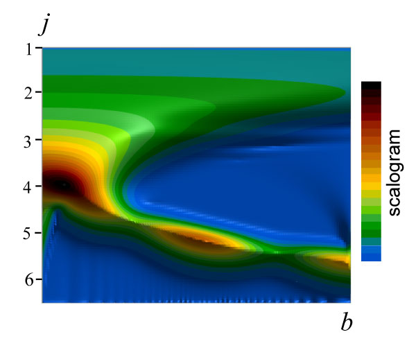
FIGURE 4. Measurements of coordinate data along a suture line. A synthetic image of an external hemi-suture was formed by combining multiple photographs (1), and a traced suture line was placed in a reference system so that its ventral and umbilical extremes were located on the x-axis separated by a distance of 10,000 pixels (2). Next, a series of y coordinates was measured along the suture line as a function of its cumulative chordal length (l) (3).
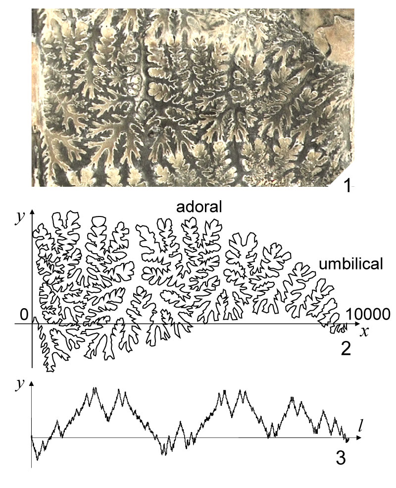
FIGURE 5. Series of y coordinates (red) and x' functions (blue). Series of x' function were detrended by subtracting the expected linear increase in x to introduce periodic boundary condition to the x-coordinate data. 1, Goniatites multiliratum. 2, Medlicottia intermedia. 3, Amphipopanoceras cf. medium. 4, Phylloceras sp.
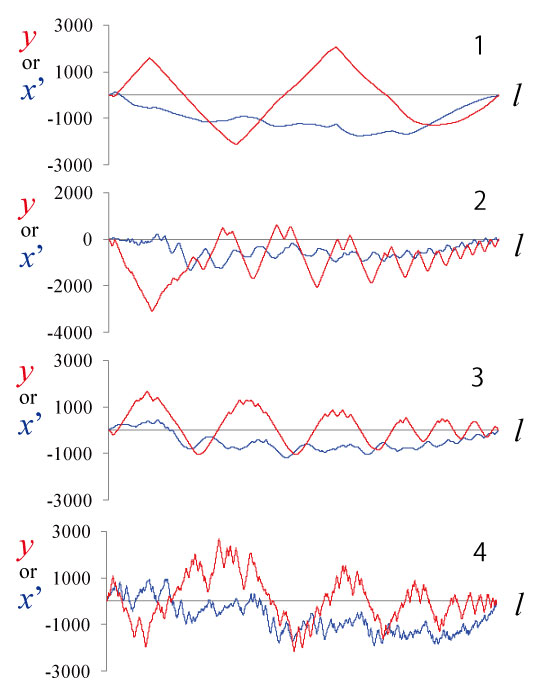
FIGURE 6. Three-dimensional contour diagrams showing the amplitudes of wavelet transforms against location (b) and frequency (h = 2j). 1, Goniatites multiliratum. 2, Medlicottia intermedia. 3, Amphipopanoceras cf. medium. 4, Phylloceras sp. 5, Gaudryceras striatum. 6, Hauericeras angustum.
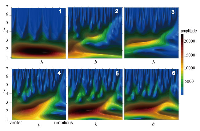
FIGURE 7. Series of shape functions obtained from repeated measurements for the identical suture of a single specimen of Gaudryceras striatum (dotted lines in red) showing that the measurement error is smaller than variation among its closely related species, i.e., G. tenuiliratum (orange), G. sp. (green), Tetragonites popetensis (blue) and T. glabrus (purple). The original digitized suture shape was illustrated for each species in the same color as the corresponding shape function.
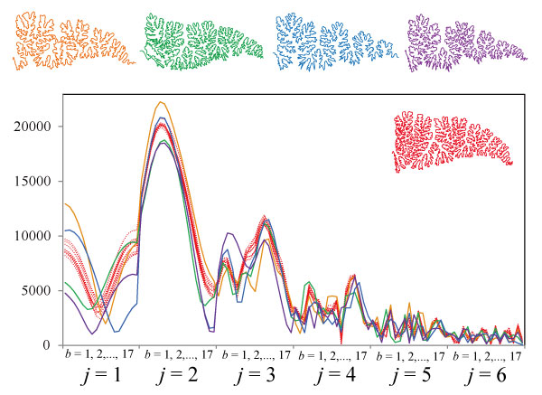
FIGURE 8. Synthetic models of suture lines represented by inverse wavelet transform with increasing number of frequencies (j). 1, Goniatites multiliratum. 2, Medlicottia intermedia. 3, Amphipopanoceras cf. medium. 4, Phylloceras sp. 5, Gaudryceras striatum. 6, Hauericeras angustum.
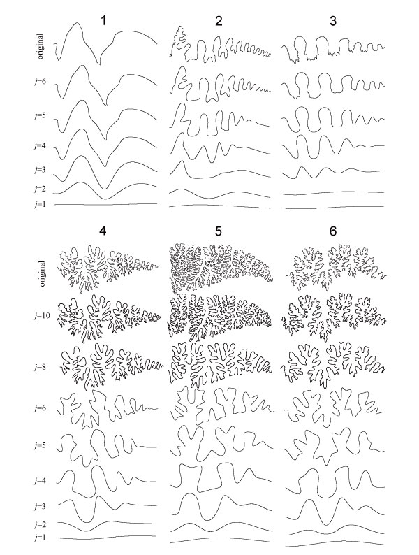
FIGURE 9. Plots of the first two principal component scores, showing examples of selected original suture shapes.
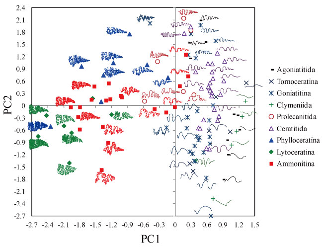
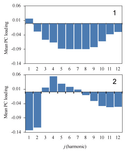
FIGURE 10. Mean of the first (1) and second (2) principal component loadings over all locations b.