FIGURE 1. Photograph of the main slab of the holotype specimen of the non-pterodactyloid pterosaur Scaphognathus crassirostris (Goldfuß, 1831) catalogued as SIPB Goldfuß 1304a from the Late Jurassic Solnhofen Lithographic Limestone of Bavaria. The skeleton is seen in right lateral view with the skull, neck, trunk, and much of the limbs preserved. The skull was prepared from both sides by Georg August Goldfuß himself (Goldfuß, 1831). Preserved soft parts are not immediately obvious in this photograph.
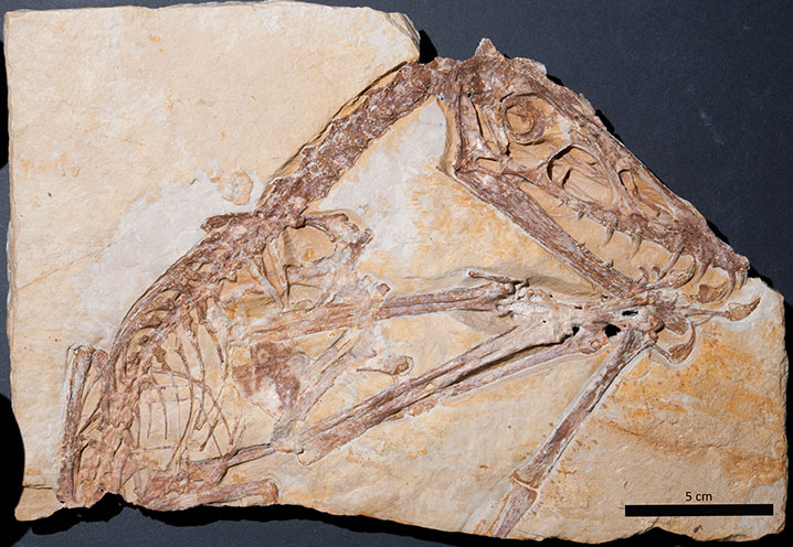
FIGURE 2. Hand-colored lithographic plates drawn by Nicolaus Christian Hohe from Goldfuß (1831) showing main slab (SIPB Goldfuß 1304a: Goldfuß, 1831, plate 8) and counterslab (SIPB Goldfuß 1304b: Goldfuß, 1831, plate 7) of the holotype specimen of Scaphognathus crassirostris. Note the high accuracy of the images but the artistic license. This consists of depicting the slab as a rectangular plate, although the actual specimen (see Figure 1) is missing the upper right corner because Goldfuß prepared the skull from both sides. In the lithographs, Goldfuß had the soft part preservation depicted and labelled (see also Figure 10).
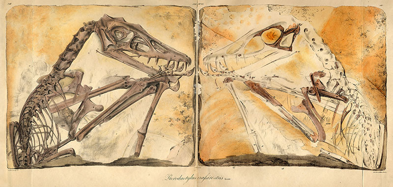
FIGURE 3. Scaphognathus crassirostris life reconstruction. This illustration was published by Goldfuß (1831) as a vignette in the lower right corner of a larger plate (tab. IX) that contains drawings of the skeletal reconstructions of Scaphognathus crassirostris. This vignette is the first life reconstruction of an extinct vertebrate in its environment in a scientific publication (Rudwick, 1992).
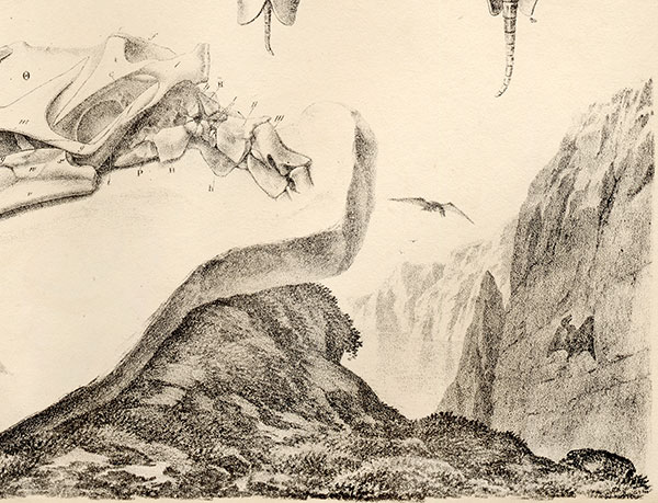
FIGURE 4. Photography setup for the mobile highlight technique of image capture for RTI/PTM imaging. 1, A single source photograph from the capturing process. The light source (flash) is positioned on the upper right side as seen on the reflectance of the black reference spheres. 2, A composite image of all flash positions is generated by the RTIBuilder software to check if spaces were missed during the capturing process. The elongate gap at the bottom is caused by one of the legs of the tripod. 3, The setup in top view. The camera is positioned above or in front of the target. The flash is moved along a contour of a virtual hemisphere at a distance of approximately three times the diameter of the object. The red dots symbolize the flash positions for the captured images. Left: Good distribution of flash positions that leaves no gaps and covers the whole object, recommended for inexperienced photographers. Right: Ideal distribution with equal distance between flash positions. 4, The setup in side view with the camera, the object, the virtual hemisphere, and flash positions. The flash positions should be at angles from at least 65° to 15° to the object. 3 and 4 are modified from Bogart (2013a).
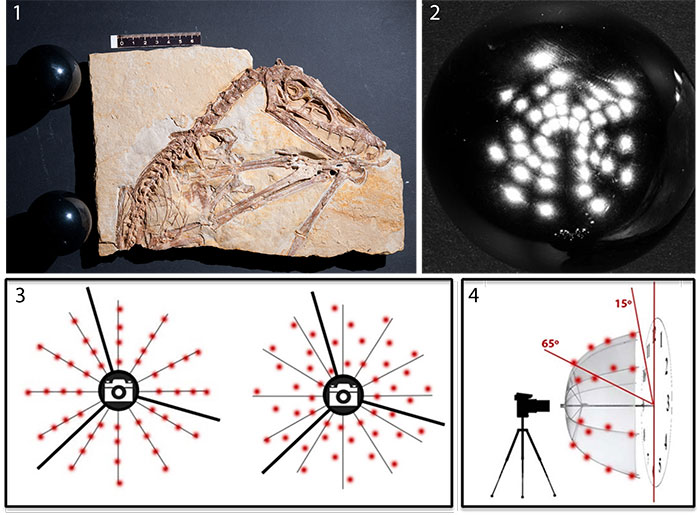
FIGURE 5. 1-4, Series of RTIViewer snapshots of the .rti file of the main slab (SIPB Goldfuß 1304a) of the holotype specimen of Scaphognathus crassirostris with low-angle light from different directions in default rendering mode. Light positions (green sphere) and a navigation overview is visible on the right side of each image. The direction of the light source can be manipulated by clicking on the green sphere or by assigning specific coordinates to the light source position.
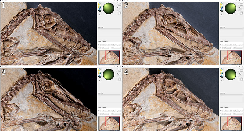
FIGURE 6. The main slab (SIPB Goldfuß 1304a) of the holotype specimen of Scaphognathus crassirostris with snapshots of different rendering modes of the.rti file. Light is from the upper left. 1, Image of main slab showing default setting (upper right) and specular enhancement with erased color information, medium specularity and highlight size (lower left). 2, Image of counter slab (SIPB Goldfuß 1304b) showing default setting (upper right) and specular enhancement with erased color information, medium specularity and highlight size (lower left). 3, Main slab viewed with color information, enhanced specularity and low highlight size. 4, Main slab viewed in normals visualization mode.
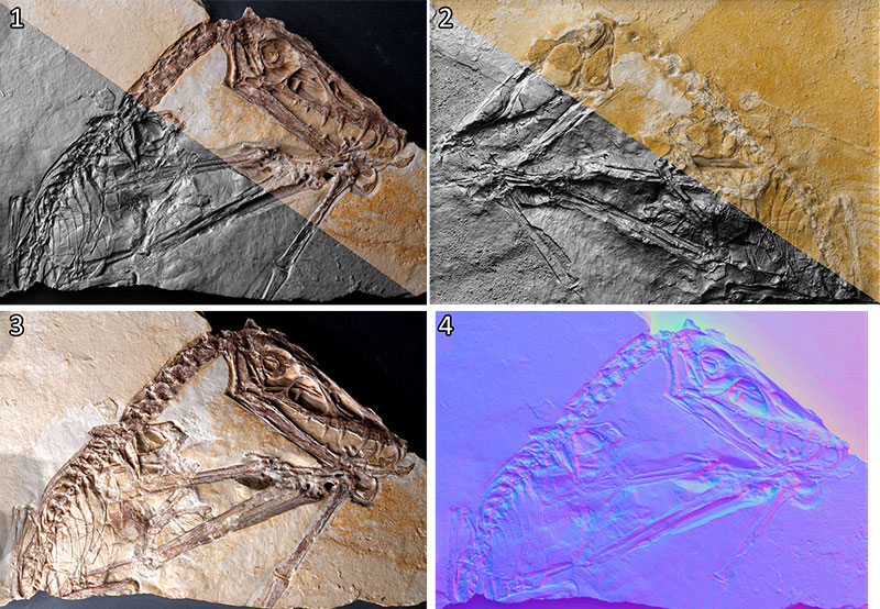
FIGURE 7. Close-ups of RTIViewer snapshots of the.rti file of the main slab (SIPB Goldfuß 1304 a) of the holotype specimen of Scaphognathus crassirostris showing soft parts with different settings and light positions. Compare to Figure 9. 1, Soft tissue with specular enhancement rendering and low-angle light. 2, Comparison of the close-up of the right arm divided between default view and specular enhancement. Note that the pycnofibers and the region of the wing membrane with the aktinofibrils is much better visible with specular enhancement 3, Specular enhancement of the region of the wing skeleton. Impressions of blood vessels and pycnofibers are clearly visible, while the aktinofibrils next to the joint of the first and second phalanx are hardly visible. 4, Dorsal region with specular enhancement. Pycnofibers are much better visible compared to the UV light image (Figure 9.2).
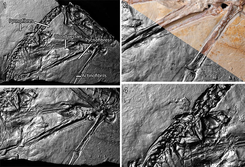
FIGURE 8. Magnification with RTIViewer enables zooming beyond the magnification of the photos by up to 200%. While this digital magnification is based on interpolation, rendering modes without color, like the specular enhancement mode, provide relatively sharp images beyond magnifications of 100% (Bogart, 2013b). 1, Blood vessels. 2, Pycnofibers ventral to the neck. 3, Aktinofibrils and displaced pycnofibers. 4, Dorsal pycnofibers.
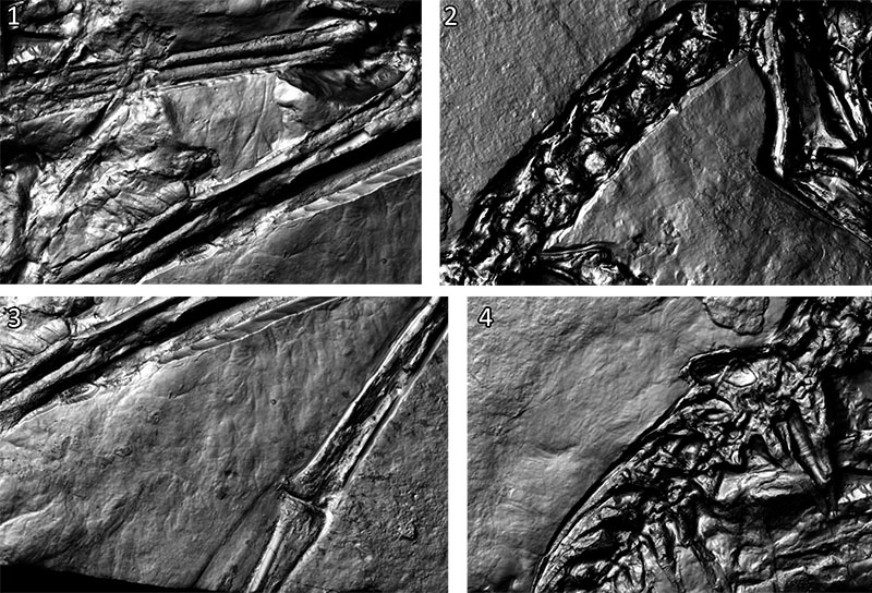
FIGURE 9. UV images of the main slab of Scaphognathus crassirostris SIPB Goldfuß 1304a modified from Tischlinger (2003). Bone apatite fluoresces yellow. 1, Main slab of holotype specimen. 2, Region of dorsal vertebral column on main slab. The light green hues suggest the presence of soft tissue. However, the impressions of the pycnofibers are not visible under UV light. 3, Wing membrane in the area enclosed by the left and right radius and ulna. Blood vessels are visible as dark lines. 4, Wing membrane aktinofibrils on the right wing finger next to the joint of the first and second phalanx. In the upper region of the wing membrane area, there are faintly visible displaced pycnofibers.
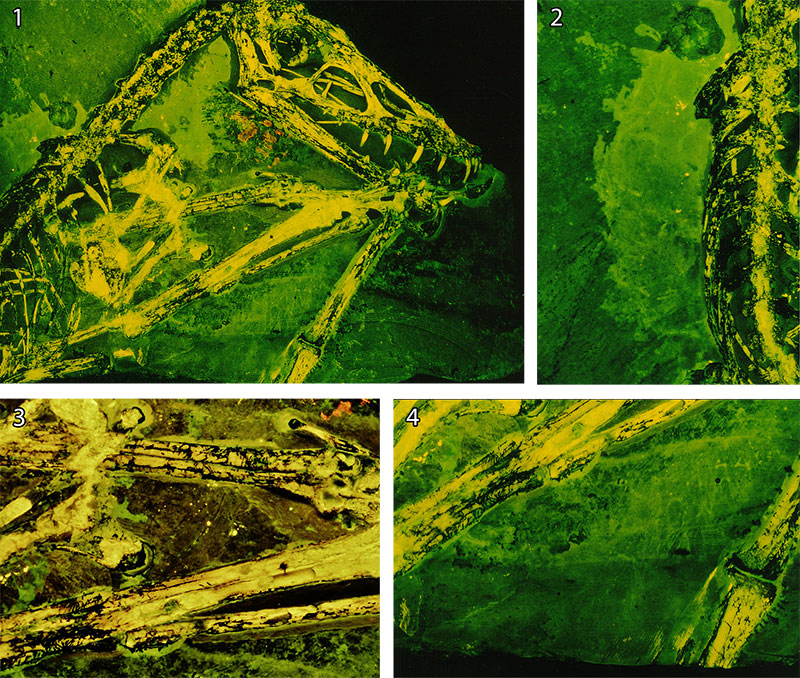
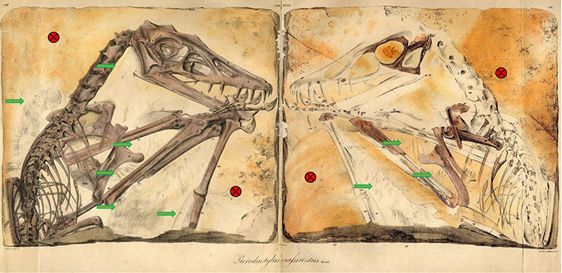
FIGURE 10. Comparison of soft tissue detection between this study and Goldfuß (1831, plates 7 and 8) on the main slab (left, SIPB Goldfuß 1304a) and counterslab (right, SIPB Goldfuß 1304b) of the holotype specimen of Scaphognathus crassirostris. Green arrows: Soft tissue depicted or described by Goldfuß and also detected by either RTI or UV light in this study. Red circles: No soft tissue detectable in this study.