FIGURE 1. USNM V7255, holotype of Edestus mirus (scale in cm). Copyright © Smithsonian Institution, all rights reserved. Used with permission.
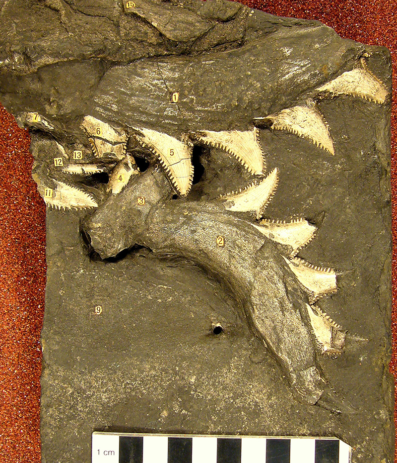
FIGURE 2. Reconstruction of the head of Edestus, illustrating the hypothesized, whole-head, vertical slashing motion. The curvature of the tooth whorls is based on the holotype of Lestrodus (originally Edestus) newtoni. Modified with permission from copyrighted artwork by G. Raham, www.biostration.com.
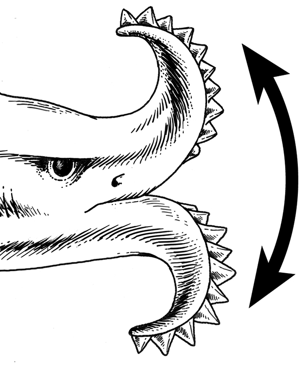
FIGURE 3. Schematic diagram showing the orientation of feeding-related scratches (red) on a tooth of Edestus for tooth whorls used in opposition (1) or in vertical slashing mode (2). Serrated crowns are blue, lingually extended bases are brown.
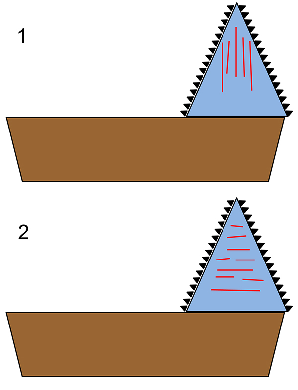
FIGURE 4. Teeth of Edestus sp. (1) and Edestus minor (2-7). TMM 40234-19 (1), TMM 40234-8 (2), TMM 40234-17 (3), TMM 40234-18 (4), TMM 40234-24 (5), TMM 40234-25 (6), TMM 40234-23 (7). Scale bars equal 1 cm.
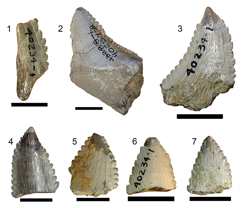
FIGURE 5. Surface features of TMM 40234-17 that are either scratches acquired in vivo or which might be mistaken for them. 1, Region near the apex of the lingual edge showing gouges and deep scratches probably made by a preparator. Scale bar equals 1 mm. 2, Region near the basal part of the lingual edge, showing a network of angular cracks. Scale bar equals 500 µm. 3, Region on the opposite side of the crown from Figure 4.3, near the serrations on the lingual edge. Shallowly incised scratches interpreted as in vivo wear are outlined in red. More deeply incised linear features are cracks. Scale bar equals 500 µm.
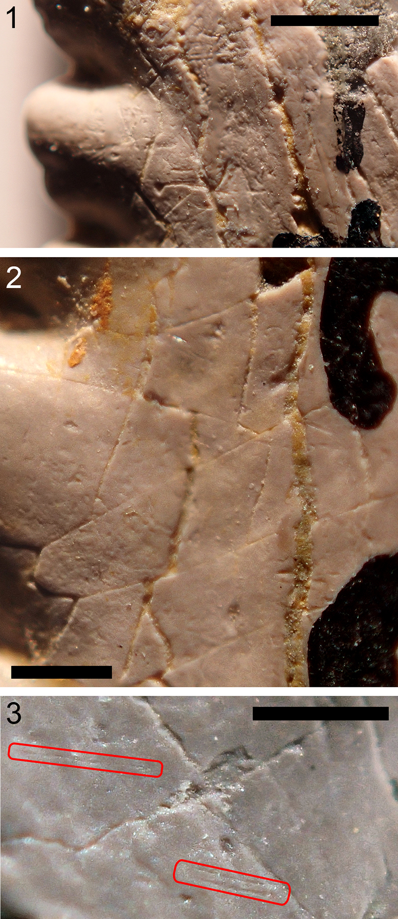
FIGURE 6. Aligned and blended mosaic of 63 images of a portion of the lateral face of TMM 40234-17. Scale bar equals 1 mm.

FIGURE 7. 1. A scratch (red) marked on the image of Figure A2.3, by use of the ImageJ program, and outlined by a yellow ellipse. 2, Parameters, including position, angle, and length, of the scratch recorded by the ImageJ program from the mark shown in 1. The only one of importance is the angle (in degrees) that describes the orientation of the scratch. Zero degrees is horizontal, to the right. The angle increases counterclockwise.
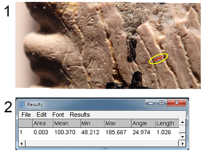
FIGURE 8. A region of the surface of TMM 40234-17 that displays several linear features interpreted as scratches acquired in vivo. Several of these are paired. Scale bar equals 500 µm.
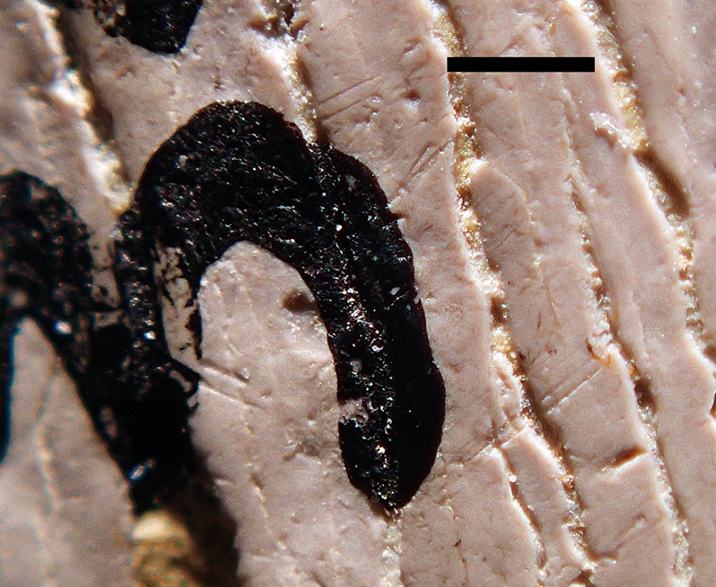
FIGURE 9. A feature interpreted as caused by in vivo wear on the surface of TMM 40234-17, outlined in yellow, consisting of three near-parallel scratches. Scale bar equals 500 µm.
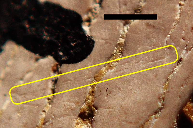
FIGURE 10. Same mosaic image as in Figure 6, with scratches marked in red. Secondary or tertiary scratches that are parallel to and associated with another nearby scratch are marked in green. Scale bar equals 1 mm.
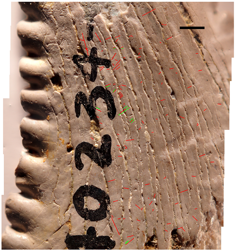
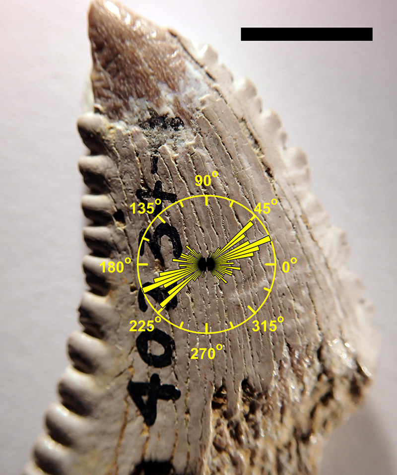
FIGURE 11. Rose plot (yellow) of angles of orientation of 107 scratches observed on surface of TMM 40234-17, overlaid on image of the same tooth. Scale bar equals 5 mm.