FIGURE 1. Measurements taken of the m1 used in this study. m1L (total molar length, taken from anterior to posterior cingulum), m1H (molar height, from the enamel/dentine junction to tip of the protoconid), m1CA (cusp angle, from anterior cingulum to tip of protoconid to the labial cingulum posterior to the protoconid).
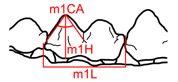
FIGURE 2. Tapirus polkensis dentary specimens from the Gray Fossil Site, representing examples of individuals within eruption series 2 through eruption series 7 in lateral view. ETMNH 605, 1. ETMNH 3694, 2. ETMNH 7899, 3. ETMNH 20488, 4. ETMNH 10383, 5. ETMNH 3519, 6. Scale bar equals 1 cm.
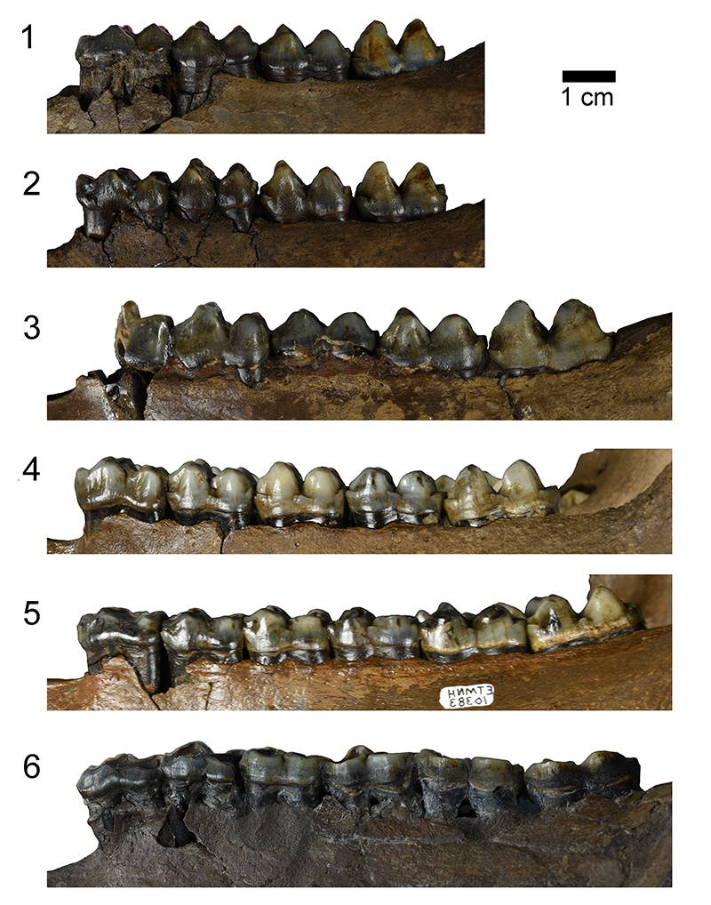
FIGURE 3. Tapirus polkensis dentary specimens from the Gray Fossil Site, representing examples of individuals within eruption series 2 through eruption series 7 in occlusal view. ETMNH 605, 1. ETMNH 3694, 2. ETMNH 7899, 3. ETMNH 20488, 4. ETMNH 10383, 5. ETMNH 3519, 6. Scale bar equals 1 cm.
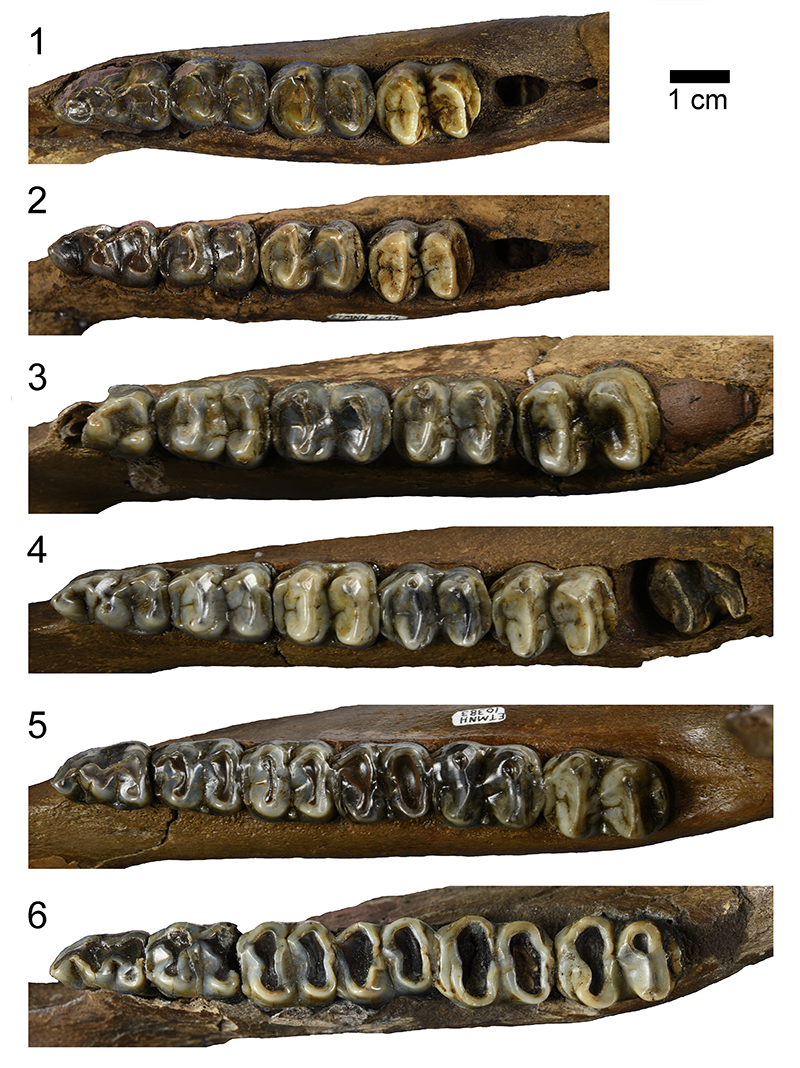
FIGURE 4. Box plot of cusp angles (in degrees) of the m1 protoconid for each eruption series of Tapirus polkensis from the Gray Fossil Site. Bars represent mean values, boxes represent interquartile ranges, and whiskers represent maximum and minimum values.
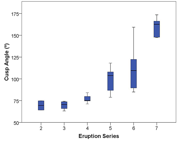
FIGURE 5. Boxplot of crown heights of the m1 protoconid for each eruption series of Tapirus polkensis from the Gray Fossil Site. Bars represent mean values, boxes represent interquartile ranges, and whiskers represent maximum and minimum values.
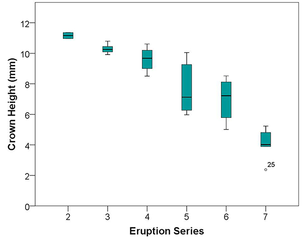
FIGURE 6. Scatter plot of m1 protoconid cusp angle versus crown height for specimens in each eruption series (ES) of Tapirus polkensis from the Gray Fossil Site. The line represents a least squares linear regression of these data, regression equation: m1CA = 20.5 – 13.13(m1H), correlation coefficient, r = 0.932.
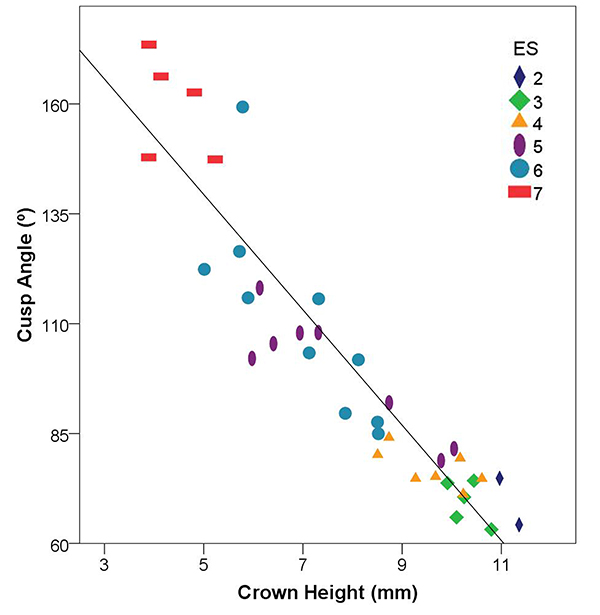
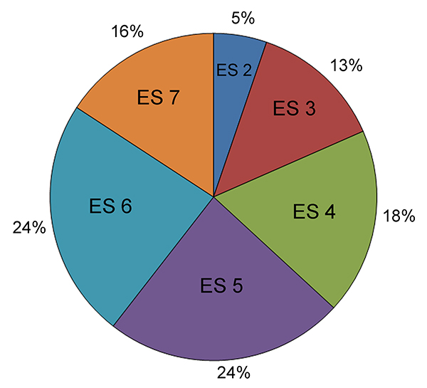
FIGURE 7. Pie chart representing the sampled population structure of Tapirus polkensis at the Gray Fossil Site, indicated by percentage of specimens in each eruption series (ES).