

APPENDIX 1.
FIGURE S1. The prototype of the Wada air scribe. The short air scribe and the cylinder were welded together, at an L-shaped configuration. The impact angle remained fixed at 90 degrees and could not be adjusted.
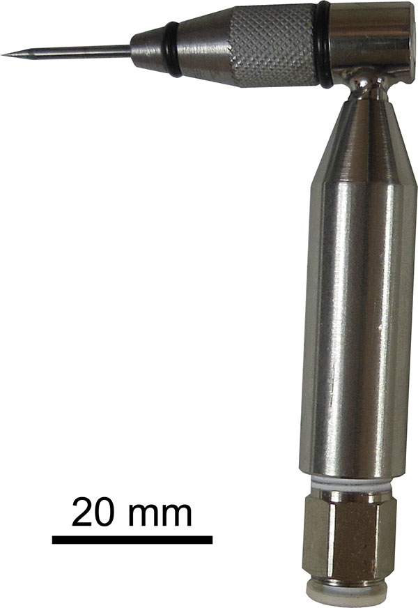
FIGURE S2. The production flow for a junction. Schematic diagrams in lateral view (upper row) and cross-sections (lower row) are shown.
1. One-fifth of the head of a fully threaded hex head screw with thread size M8 (component 1 in Figure 2) was utilized as a base material of the junction part. The outline of the junction is depicted as a dotted line.
2. The hexagonal head of the screw was then shaped into the junction form.
3. A tapped hole with the thread size M4 was drilled.
4. A clearance hole with a diameter of 1 mm was drilled.
5. The diameter of the clearance hole was reduced at the surface, creating an orifice with a diameter of 0.5 mm.
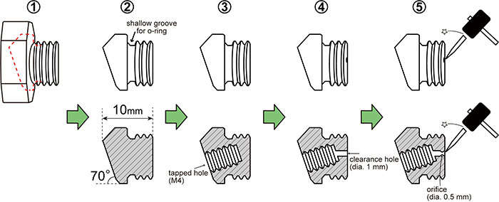
FIGURE S3. The production flow for a cylinder. Schematic diagrams in lateral (upper row) and front (lower row) views are shown.
1. A coupling nut, measuring 25 mm in length with thread size M8 (component 2 in Figure 2), was utilized as the base material for the cylinder part.
2. The corners of the coupling nut were rounded off and the coupling nut was shaped into a cylinder through grinding.
3. The width of the cylinder was adjusted to 10 mm by chamfering the left and right lateral sides. A small 3 mm diameter depression was created on the right side of the lateral surface.
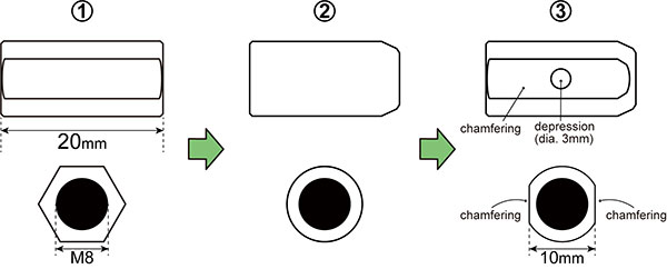
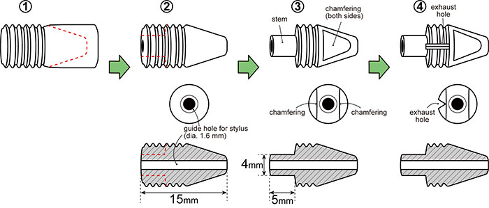
FIGURE S4. The production flow for a bushing. Schematic diagrams in lateral (upper row) and front (middle row) views and cross-sections (lower row) are shown.
1. A middle part of a partially threaded socket head screw with thread size M8 (component 3 in Figure 2) was utilized as a base material for the busing part. The outline of the bushing is depicted as a dotted line.
2. The non-threaded portion was grounded into a conical shape and a guide hole (1.6 mm in diameter) for a stylus was drilled in the center of the bushing. The outline of the stem is indicated by a dotted line.
3. The opposing sides of the bushing tip were chamfered. The threaded portion was ground to make a stem, which is 5 mm in length and 4 mm in width.
4. A narrow notch (exhaust hole) was made on the threaded portion of the bushing on one side.
APPENDIX 2.
Three-dimensional image of a junction (STL). Available for download as zipped file.
APPENDIX 3.
Three-dimensional image of a cylinder (STL). Available for download as zipped file.
APPENDIX 4.
Three-dimensional image of a bushing (STL). Available for download as zipped file.
APPENDIX 5.
Three-dimensional image of a Wada air scribe (STL). Available for download as zipped file.
APPENDIX 6.
Three-dimensional image of a handle form 1 (STL). Available for download as zipped file.
APPENDIX 7.
Three-dimensional image of a supporting rod of a handle form 2 (STL). Available for download as zipped file.
APPENDIX 8.
Three-dimensional image of a body holder of a handle form 2 (STL). Available for download as zipped file.
APPENDIX 9.
Three-dimensional image of the Wada air scribe with handle form 1 (STL). Available for download as zipped file.
APPENDIX 10.
Three-dimensional image of the Wada air scribe with handle form 2 (STL). Available for download as zipped file.
