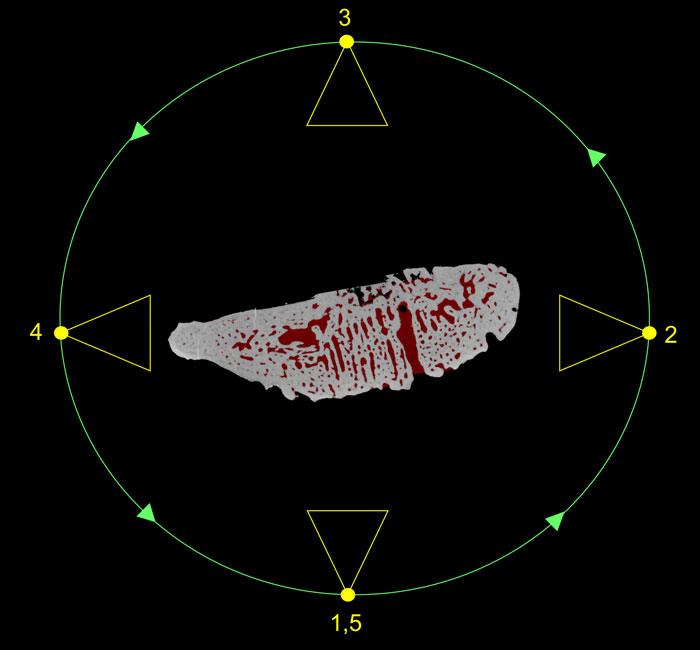
FIGURE 1. Micro-CT can be used to" virtually" extract fossils. (1.1) Photo of the shark tooth in matrix and (1.2) sectioned micro- CT rendering after virtual preparation from rock matrix.
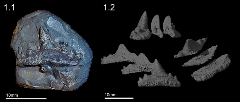
FIGURE 2. A simple example of back projection based on two digital projections at 90o to each other. Corresponding rows of pixels from each projection are used to create an X-ray transmission profile. Profiles are used to create digital images of the row that are then back projected (i.e., smeared) onto one another to create a 3D CT slice. In this example the cylindrical objects appear in the image as cubes, but the shape would be resolved if more projections were analysed. This process is repeated for every slice (pixel row) in the scan.
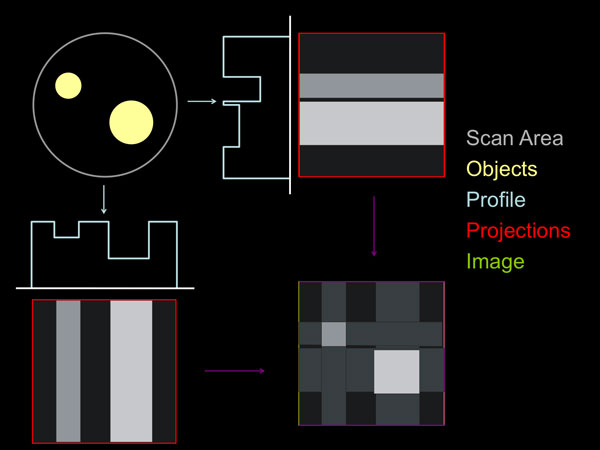
FIGURE 3. Micro-CT grey value frequency distribution plot. The graph reveals three peaks representing air, matrix and fossil. The tooth was calibrated by applying a global threshold at the minima, which separated the fossil peak (vertical red line).
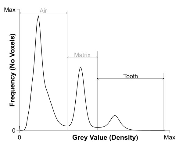
FIGURE 4. Virtual preparation (segmentation) of the fossil was carried out in three steps. (4.1) Surface determination (4.2) ROI growing and (4.3) masking. (4.4) The vascular system was extracted using a combination of masking and region growing.
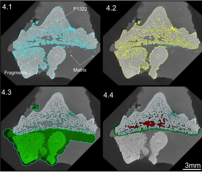
FIGURE 5. Virtually prepared fossil rendered with lights, colour and perspective. (5.1) Fossil and vascular system, (5.2) transparent fossil and vascular system and (5.3) vascular system.
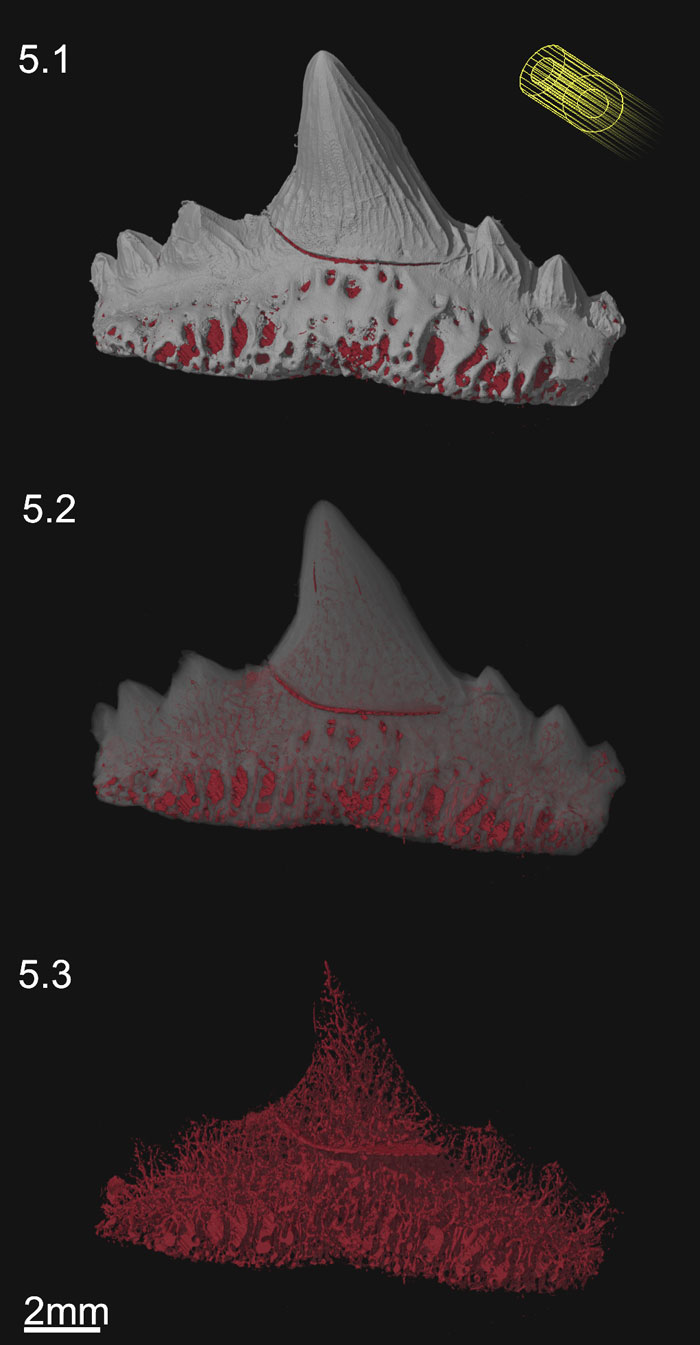
FIGURE 6. Stereo-anaglyph of virtually prepared fossil. Rendered with lights, colour and perspective. The image can be viewed in three-dimensions using red-cyan (or red green) spectacles.
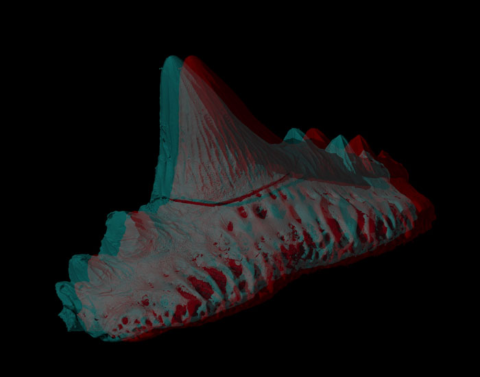
FIGURE 7. Animation keyframer and key frames used to produce supplementary movies 1 and 2. The camera (yellow) follows a circular path (green) around the tooth (shown as a cross section). At each key frame the camera is rotated toward the specimen. At key frames 1 and 2 the tooth is opaque but at 3, 4 and 5 it is transparent. The key frame interpolates these settings as a single camera rotation about the tooth with a transparency developing between key frames 2 to 3. This reveals the underlying vascular structure.