

 Insights into the controversy over materials data for the comparison of biomechanical performance in vertebrates
Article number: 18.1.10A
https://doi.org/10.26879/509
Copyright Palaeontological Association, March 2015
Author biographies
Plain-language and multi-lingual abstracts
PDF version
Submission: 1 September 2014. Acceptance: 23 February 2015
{flike id=1095}
ABSTRACT
Mechanical comparison of different species is performed with the help of computational tools like Finite Element Analysis FEA. In palaeobiology it is common to consider bone like an isotropic material for simulations but often real data of bone materials is impossible to know. This work investigates the influence of choice of bone materials properties over the results of simulations, showing when and why the materials data are relevant and when the selection of these data becomes irrelevant. With a theoretical approach from continuum mechanics and with a practical example the relationship between material data and comparative metrics like stress, strains and displacements is discussed. When linear and elastic material properties are assumed in a comparative analysis, the effect of the elastic modulus of the material is irrelevant over stress patterns. This statement is true for homogeneous and inhomogeneous materials, in this last case the proportion between the different materials properties must kept constant. In the case of the strains and displacements, there is an inverse proportionality kept constant, between the values of the metrics and the changes in the elastic modulus. These properties allow comparative studies without considering the real elastic materials properties.
Lluís Gil. Universitat Politècnica de Catalunya - BarcelonaTech, 08222, Terrassa, Spain Lluis.gil@upc.edu
Jordi Marcé-Nogué. Universitat Politècnica de Catalunya - BarcelonaTech, ETSEIAT, c/colom 11, edifici TR45, 08222, Terrassa, Spain
and Institut Català de Paleontologia, Edifici ICP, Universitat Autònoma de Barcelona, Campus de Bellaterra, 08193, Cerdanyola del Vallès, Spain, Jordi.marce@upc.edu
Montserrat Sánchez. Universitat Politècnica de Catalunya - BarcelonaTech, 08222, Terrassa, Spain, Montserrat.sanchez@upc.edu
Keywords: finite element analysis; materials properties; bones; continuum mechanics; comparative analysis
Final citation: Gil, Lluís, Marcé-Nogué, Jordi, and Sánchez, Montserrat. 2015. Insights into the controversy over materials data for the comparison of biomechanical performance in vertebrates. Palaeontologia Electronica 18.1.10A: 1-24. https://doi.org/10.26879/509
palaeo-electronica.org/content/2015/1095-controversy-in-materials-data
INTRODUCTION
In the last 10 years, the potential of finite element analysis (FEA) as a simulation technique in palaeobiological research has had a significant impact in the scientific community because it has the potential to provide keys to understanding the biomechanical behaviour of living and extinct taxa. FEA is a computational methodology of mechanical simulation based on a numerical analysis on the principle of dividing a system into a finite number of discrete elements to which equations are applied (Bathe, 1996). The FEA model enables researchers to obtain the stress-distribution and strain-distribution patterns and the displacements of various models by simulating the loadings and forces involved in biomechanical behaviours.
According to (Anderson et al., 2012), the results obtained in the FEA models are applied to solving functional questions about biting and running, analysing form and function, inducing morphological changes and evaluating their effects on the model performance or exploring the morphospace. Alternatively, according to (Rayfield, 2007), researchers can investigate questions of optimality, adaptation and constraint in the skeleton, or a stress-strain analysis can be used to compare the effect of modifying, adding or removing structures in the model to test the importance of evolutionary change. To date, several studies have focused on comparing models of various species using computational mechanics: these include the early works (Dumont et al., 2005; Macho et al., 2005) and the more current works (Oldfield et al., 2012; Parr et al., 2012; Rivera and Stayton, 2013). Most of these studies were performed in the context of comparative biology, in which various living and extinct taxa can be compared to understand the evolution of species (Curtis et al., 2011; Degrange et al., 2010). In the context of biomechanics, the principal use of such models in palaeobiology is to compare the behaviour of various species to infer the mechanical behaviour and function and relate them to various ecological adaptations (Fortuny et al., 2011, 2012). Recently, (Walmsley et al., 2013) indicated an interest in testing the sensitivity of the results obtained by FEA with various input parameters and a review of (Bright, 2014) focus on the material properties most of the variations in the results obtained in the strains. Other works have studied the influence of the materials properties of biological tissue (Cox et al., 2011), sutures (Kupczik et al., 2007) or the value of the applied loads (Tseng et al., 2011).
Here, we focus on the influence of bone properties on the results of a FEA model. In palaeobiology, most reports have considered bone to have isotropic behaviour. This assumption is usually accurate enough (Doblaré et al., 2004), although several works assume nonlinear properties (Sharir et al., 2008) or orthotropic behaviour (Porro et al., 2011). The definition of these behaviours in an FEA model relies on the usage of constants, such as the elastic modulus (E), in the constitutive equations of the material. These constants have a specific numerical value for each different material.
The most common and simplest way to obtain the constants is by applying destructive tests to the specimens (see a review of mechanical tests for the study if the mechanical behaviour of bones in (Sharir et al., 2008)). Destructive tests were performed until failure to record the materials behaviour under various loads and to make it possible to define the constitutive equation of the material. Nevertheless, in biological sciences, and especially in vertebrate structures, preserving the integrity of the specimens is mandatory when we have limited specimens to analyse. In this case, nondestructive tests characterised by no damage should be used. In line with this, ultrasonic testing is a nondestructive, successful technique that has been used in engineering fields to determine the elastic constants of materials, included the elastic constants of bone, to determine the constitutive equations of materials (Rose et al., 2005). In spite of the development of these technologies for determining the materials properties of bone, knowledge is lacking about most of the extant species in the animal kingdom, and it is obviously impossible to test the mechanical properties of all of the fossil record. This fact leads researchers to rely on hypotheses about materials considerations in the FEA models. It is common to use the materials properties of reliable, related data - for example (Neenan et al., 2014) or (Piras et al., 2013) - and the use of linear, elastic and isotropic properties because of the difficulty to obtain more complex information. In addition, these assumptions must be qualified by lengthy discussion, justification and references citing the assumed materials properties.
Particularly, this lack of information means that, for example in (Fortuny et al., 2011), cranial materials properties of crocodiles were used because the ossification of their skeleton shows similarities to all of the different extinct temnospondyls analysed, which are a group of early tetrapods that lived during the Palaeozoic and Mesozoic periods. And in (Marcé-Nogué et al., 2013), the same materials properties of bovine haversian bone were considered for four jaws of four species of extant bovids (Mammalia, Ruminantia) that have been analysed in spite of their differences because it was the information available in (Reilly and Burstein, 1975).
At this point, we demonstrate that in most of the cases, there is no necessity to hypothesise about materials or create justifications. In certain cases, the mechanical performance characterised by the stresses, strains and displacements is not directly affected by the type of material employed in the simulations. Finally, we elucidate when and why materials data are relevant and when the selection of these data can be ignored.
MATERIAL AND METHODS
Basic Equations
Continuum mechanics is the branch of mechanics that deals with the analysis of the mechanical behaviour of materials considering that elastic bodies will deform when loads are applied to them; When it happens, the applied load is distributed internally in a stress field which distributes all the forces (Stress = Force/Area) around the whole body (Mase and Mase, 1999). Elasticity is the tendency of solid materials to return to their original shape, after being deformed, when this load is released. Elastic problems are driven by known equations of equilibrium (Mase and Mase, 1999) with three relevant quantities that meet the equations: displacement field, strain field and stress field.
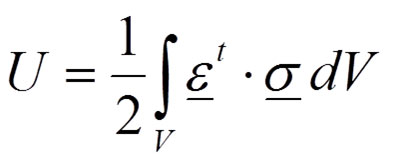
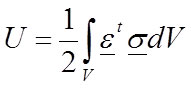
The desired situation for biological systems is the elastic behaviour when no permanent deformation appears after loading. For elastic bodies, in the absence of temperature variations, the strain energy - or internal work - represents the energy stored by the system undergoing deformation (Equation 1):
 1
1
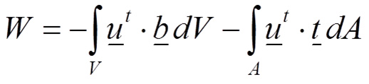
where the total strain energy in a body is U, σ is the stress field and ε is the strain field. On the other side, the total external work is performed by the external forces that are loading the body (Equation 2):
 2
2
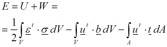
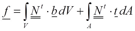
Where u is the displacement field, b represents the volume forces and t represents the surface forces. Therefore, the total energy E of the body is defined in Equation 3 balancing the internal work (strain energy U) and the external work W:
 3
3
According to the principle of minimum energy (second law of thermodynamics), the equilibrium of this system of forces is reached when the body is subjected to the minimum energy. Therefore, equilibrium exists when there is a field of displacements u that fulfils the boundary conditions imposed in the problem and minimises the total energy.
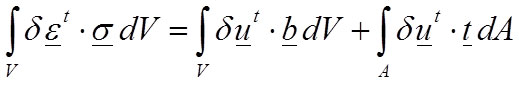
Nevertheless, the equations can be rewritten in the so-called “weak form” which is based in the differential formulation and is the most known equation to raise the equilibrium of the elastic problem (Reddy, 2002). The weak form is also known as the principle of virtual work (Equation 4):
 4
4
where δu is a field of virtual displacements, and δε is a field of virtual strains.
Discretisation in Finite Elements
There are few analytical solutions for a limited number of theoretical and unrealistic elastic problems that solve the principle of virtual work. These solutions are mainly in very simple geometries and, hence, numerical solutions are necessary to solve the complex geometries that biological systems usually present. The finite element method is a good mathematical method to solve the weak form of the elastic problem (Zienkiewicz, 1971) in any geometry and is adequate for complex geometries. The method divides the continuum model into a discrete model by meshing the body with the so-called finite elements and enabling a matrix formulation. The displacement field u can be represented by Equation 5:
![]() 5
5
where N is a matrix of interpolation functions (called shape functions), and a is the value of the displacements in the nodes of the mesh of finite elements. Equation 5 makes it possible to compute the displacement at any point in the body given the values of its coordinates (x, y, z).
According to the elastic hypothesis, the strains are the derivatives of the displacements and can be obtained from Equation 6, where B is the matrix of the shape function derivatives:
![]() 6
6
The materials properties are determinant for the relationship of stresses and strains, and it is stated by a set of equations called constitutive equations.. The elastic constitutive equation does not include creep at a constant stress or relaxation at a constant strain, and for elastic materials, the linear constitutive model for the infinitesimal strains is the generalised Hooke’s law (Mase and Mase, 1999). It is defined by Equation 7 for a continuum and in the discrete form:
![]() 7
7
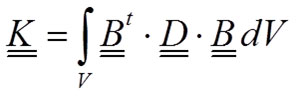
where D is the constitutive matrix of the material of the elastic constants. Therefore, rewriting the continuum equation (Equation 4) in a discrete form using the matrix formulation, a system of equations results (Equation 8). Details can be found in (Zienkiewicz et al., 2013).
![]() 8
8
where the so-called stiffness matrix K is:
 9
9
and the vector of forces f is:
 10
10
Influence of Elastic Materials Constants in the FE Equations
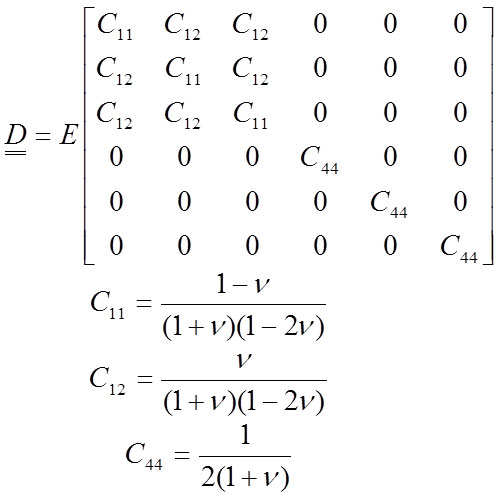
A material is isotropic when the materials properties are identical in all directions from a point. A material is orthotropic when there are three orthogonal planes of materials symmetry. In this case, the material acts similarly in certain directions. As mentioned earlier, most works performed in palaeobiology consider bone to have isotropic behaviour. An isotropic material is characterised by two independent elastic constants, the elastic modulus E and the Poisson coefficient V , and is defined according Hooke’s law in a matrix form (Equation 11). This matrix form is relating all the stresses and the strains in Equation 7.
 11
11
The Poisson coefficient is approximately 0.4 in most vertebrate bones (Reilly and Burstein, 1975), but the value of the Poisson coefficient V is not crucial. Nevertheless, the value of E largely determines the solution of the system (Equation 8).
Therefore, the study developed in this work analyses the impact of using the two different models for bone properties: homogeneous and inhomogeneous.
Bones as an isotropic, homogeneous material. When a body is considered to have homogeneous properties, the entire body has the same constitutive equation, and (Equation 11) can be defined with a proper elastic modulus E (see (Fortuny et al., 2011) for an example of homogeneous bone in FEA models). The solution of the equilibrium equation (Equation 8) is:
![]() 12
12
where the strain can be computed according to (Equation 13), and the stress can be computed according (Equation 14):
![]() 13
13
![]() 14
14
But, when the material has a different elastic modulus λ (times E):
![]() 15
15
the constitutive equation (Equation 11) changes to this form:
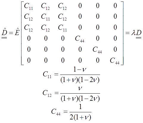 16
16
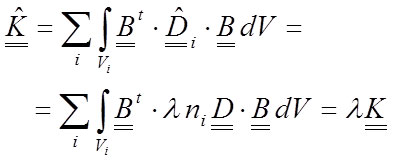
The stiffness matrix of the system (Equation 9) will change, and taking into account that λ is a scalar value, the new stiffness matrix can be written as a proportion of the old matrix:
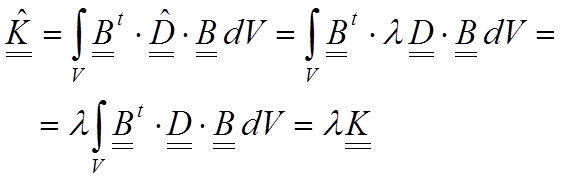 17
17
As a result, the nodal-displacement solution will change to Equation 18, resulting in a change in the displacement values obtained:
![]() 18
18
The new strain field can be expressed as:
![]() 19
19
However, notice that the stress field will remain unchanged:
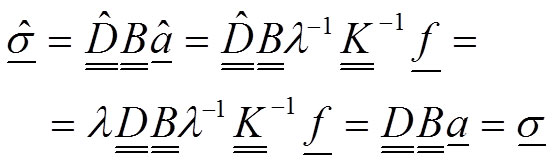 20
20
The mathematical demonstration in this part results in the important conclusion that 1) the value of the elastic modulus does not influence the results of the stress field, whereas 2) the change of the value for the elastic modulus induces an inverse proportion change λ -1 for the displacements and strains.
Bone as an isotropic, inhomogeneous material. Inhomogeneous properties mean that the body is composed of distributed masses with different isotropic properties (See Aquilina et al., 2013 for an example of an inhomogeneous bone FE model). In this case, the expressions (Equations 5-11) must consider that the model is composed of i different materials. Every elastic modulus Ei can be referenced to a material E for which n i is a scalar value that is different for each i-material:
![]() 21
21
For the reference material, the constitutive equation is the same expression as (Equation 11), and the constitutive matrix of every material can be written as:
![]() 22
22
Hence, the expression of the stiffness matrix (Equation 9) is calculated by adding the contribution of each material:
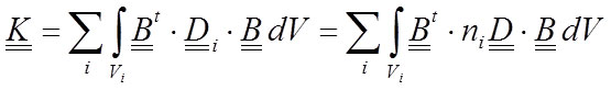 23
23
The displacement vector becomes:
![]() 24
24
The strain field in each materials area is computed as (Equation 25), and the stresses for every materials area are computed as (Equation 26):
![]() 25
25
![]() 26
26
If we modify the expression of each material λ times as in the previous demonstration, we achieve the following constitutive equation for the reference material:
![]() 27
27
Consequently, for the rest of materials, we obtain:
![]() 28
28
The new stiffness matrix will change, and taking into account that λ is a scalar, the new stiffness matrix can be written as a proportion of the old:
 29
29
As a result, the nodal-displacement solution will become Equation 30 for the displacement field and Equation 31 for the strain field:
![]() 30
30
![]() 31
31
However, when computing the stresses and considering each material found (according to Equation 28 and the fact that λ is an scalar):
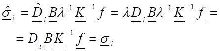 32
32
Equation 32 demonstrates that the stresses are not affected by the change in the elastic modulus of the material. This means that the reference value of the elastic modulus in the simulation of an inhomogeneous material is not relevant. Nevertheless, notice that a strong condition has been used: all materials have been modified the same λ value. This necessitates that the relative value between the materials must be maintained. The value of n i must be known. Thus, when inhomogeneous materials are simulated, certain limitations over the values of the elastic modulus are assumed. The change in the value of the elastic modulus also induces an inverse proportion change for the displacements and the strains as in the previous analysis.
Principal stresses and strains. In the use of metrics as maximum/minimum stresses or strains for comparison between biological systems, for example (Brassey et al., 2012), material data will not arbitrarily affect the metric. Maximum and minimum values come from the diagonalization of stress/strain tensors finding eigenvalues and eigenvectors (principal directions). If stress values are identical according to Equations 20 and 32, therefore maximum and minimum values (eigenvalues) will perfectly match, and eigenvectors will be the same. In the case of strain, according to Equations 19 and 31, values are proportional by a λ -1 scalar. Hence, the maximum and minimum values are scaled and eigenvalues depend on this scalar. Because values are scaled by a real number, eigenvectors will coincide and principle directions will not be affected. Therefore, strain orientations will maintain and comparison can also be done.
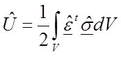
Strain energy. Another interesting metric that has been used in comparing the performance of different vertebrate models is the strain energy: for example (Dumont et al., 2011). Strain energy was defined previously in Equation 1 and for a material with elastic modulus E is:
 33
33
For a material with a different modulus (λ times E):
 34
34
According to Equations 19 and 20 (for an isotropic and homogeneous material) or 31 and 32 (for an isotropic and inhomogeneous material) it is possible to rewrite the strain energy to:
 35
35
Strain energy is affected by λ -1 and the change of the value for the elastic modulus induces an inverse proportion change λ -1 for the strain energy.
Finite Element Model
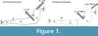 We used planar 2D models of extant bovids (Mammalia, Ruminantia), such as Connochaetes taurinus and Alcelaphus buselaphus , both of which are housed at the American Museum of Natural History (AMNH, New York). The models were used and described previously in (Marcé-Nogué et al., 2013), and according to the assumption of the usual simplifications in 2D analysis, constant thicknesses of 20.88 mm and 16.97 mm, respectively, were assumed. The models were solved using the ANSYS FEA Package v.14.5 for Windows 7 (64-bit system) to obtain the von Mises stresses, strains and displacements of the 2D model. As points of interest, two points P (the most mesial point of the first premolar at the alveolus) and Q (the most distal point of the third molar at the alveolus) were placed in the jaws to record the numerical values of the results (Figure 1). The values of the forces were also defined in (Marcé-Nogué et al., 2013) according to the scaling method proposed and were applied both in the masseter and in the temporalis in the directions appropriate for the relative direction of force during chewing.
 Although there are several results produced by FEA (different types of stresses, strains, displacements, etc.), the most common magnitude in the study of vertebrate structures is the equivalent von Mises criterion. This is an isotropic criterion that may be the most accurate for predicting the fracture location when isotropic materials properties are used in the cortical bone (Doblaré et al., 2004). For this reason, in this work, we will display the results of the equivalent von Mises stress, the equivalent von Mises strain and the displacements when studying the influence of the elastic material properties.
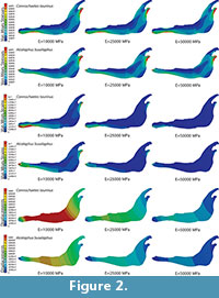
To study this influence, two FE analyses were performed. The first had a homogeneous, linear, elastic and isotropic material for the entire jaw, and the second (shown in Figure 2) divided the bovine jaw into three different areas with three different linear, elastic and isotropic materials to generate an inhomogeneous materials distribution inside the jaw.
RESULTS
Case Study A: Homogeneous Material
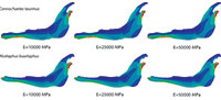
Plane models of Connochaetes taurinus and Alcelaphus buselaphus were solved with nine different values of elastic modulus E between 10 GPa and 50 GPa, which are normal values for bone (Sharir et al., 2008). Poisson’s ratio is assumed to be 0.4 for bovine haversian bone (Reilly and Burstein, 1975). The von Mises stress distribution, von Mises strain distribution and displacements in the entire jaw are shown in Figure 2 for three different E values. The change in the coloured scale of the legend is according to the inverse proportionality between strains and displacements (Equations 18 and 19), and the same scale is retained for the von Mises stress (Equation 20). The results show that the displacement field, the strain distribution and the stress distribution are qualitatively identical and quantitatively proportional.
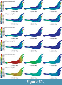 In the supplementary information (Figure S1), the von Mises stress and the von Mises strain distributions and the displacement field for the entire jaws are also given when the coloured scale in the legend is the same for the three cases. In this figure, it is clear that the values are dissimilar.
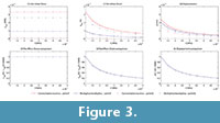
The von Mises stress, strain and displacements at points P and Q (figure 3) were recorded, and the variation in these values preceding the change in E values are shown in Figures 3.1, 3.2 and 3.3 (see Table S1 for numerical results).
In Figures 3.4, 3.5 and 3.6, the value of the proportion between the von Mises stress for the current value of the elastic modulus and the von Mises stress by the reference elastic modulus (10000) is also recorded (see Table S2 for numerical results). This value and the same value, except for strains and displacements, are drawn in the figure preceding the variation in the elastic modulus. This shows that the relationship between the reference value of the elastic modulus (10000 MPa) and the other values maintain the same proportion for all cases, which is constant for stresses and the inverse linear proportion of the elastic modulus for the strains and displacements.
The numerical results obtained for maximum and minimum principal stress and strains and for strain energy are also available in Table S3 and Table S4 of supplementary information. They show the same proportion with the material established previously.
Case Study B: Inhomogeneous Material
 Plane models of Connochaetes taurinus and Alcelaphus buselaphus were divided into three areas where different bone properties were applied to define an inhomogeneous material in the entire jaw (see Figure 1 with the three areas differentiated). The values used in these three parts follow the proportions E 1 =λ 1 ·E, E 2 =λ 2 ·E and E 3 =λ 3 ·E, where λ 1 =0.5, λ 2 =1 and λ 3 =2. In this case, nine different values of the elastic modulus E between 10 GPa and 50 GPa, and a Poisson’s ratio of 0.4, were considered.
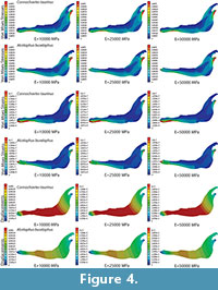
The von Mises stress distribution, von Mises strain distribution and displacements in the whole jaw are shown in Figure 4 for three different E values. The change in the coloured scale of the legend is according to the inverse proportionality between the strains and displacements (Equations 30 and 31), and the same scale is kept for the von Mises stress (Equation 32). The results show that the displacement field, the strain distribution and the stress distribution are qualitatively the same and quantitatively proportional.
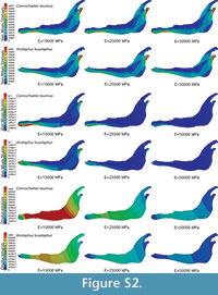
 In the supplementary information (Figure S2) the von Mises stress and von Mises strain distributions and the displacement field for the entire jaws are also given when the coloured scale is the same for the three cases. In this figure, it is clear that the values are different.
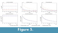
The von Mises stress, strain and displacements in points P and Q were recorded, and the variation of these values preceding the change in the E values is shown in Figures 5.1, 5.2, and 5.3 (see Table S5 for numerical results). In Figures 5.4, 5.5 and 5.6, the value of the proportion between the von Mises stress for the current value of the elastic modulus and the von Mises stress by the reference elastic modulus (10000) were recorded (see Table S6 for numerical results). These values and the same values, except for strains and displacements, are drawn in the figure showing the variation in the elastic modulus. This shows that the relationship between the reference value of the elastic modulus (10000 MPa) and the other values maintains the same proportion for all cases, which is constant for the stresses and the inverse linear proportion of the elastic modulus for strains and displacements.
The numerical results obtained for maximum and minimum principal stress and strains and for strain energy are also available in Table S7 and Table S8 of supplementary information. They show the same proportion with the material established previously.
DISCUSSION
 The importance of FEA in the study of biomechanical behaviour in a comparative context for vertebrate structures has been highlighted before, and in the cases solved here, the role of the variations of the elastic materials constants has been tested.
In case study A, for an isotropic homogeneous material, the value of the elastic modulus is determinant for the values of the displacements and strains and is not determinant for the values of the stresses. Notice that the stress values of the examples (Von Mises stresses and principal stresses in supplementary information) are identical for any elastic modulus. Moreover, for a comparison between the patterns of the strains and displacements, the elastic modulus might also be considered irrelevant. The displacement and strain values change (Von Mises strains and principal strains and strain energy in supplementary information), but these magnitudes maintain a common distribution pattern (as Strait et al., 2005 noted empirically). The proportionality of the values enables the comparison of computational models.
 This is important when comparing the von Mises stress distribution of two different bovine jaws (as Connochaetes taurinus and Alcelaphus buselaphus) in the absence of information on the material properties of the jaws. A fair approach is to use relevant information from (Reilly and Burstein, 1975) about the properties of bovine haversian bone. Nevertheless, assuming elastic behaviour, it is not necessary to have a close materials value because the results of the stress values and distribution will be identical regardless of the value chosen. The stress results are not affected by the value of the elastic modulus.
In the example cited in the introduction (Fortuny et al., 2011), the cranial materials properties of crocodiles were used for various extinct temnospondyls (a group of early tetrapods that lived during the Palaeozoic and Mesozoic periods). The decision to use this materials property in the FEA model was not crucial for the results because the values and the distribution of the von Mises stresses would be the same regardless of the materials definition. And, although the values of the displacements obtained in the jaws will be different as a function of the values of the elastic modulus, in the different jaws, the displacement values maintain proportionality, and the pattern distribution can also offer interesting insights.
In case study B for an isotropic inhomogeneous material, the elastic modulus must be defined for each of the materials. As in the other case, a free choice of the elastic modulus values will induce an incorrect displacement and the exact value of the strain but not of the stress. The value of the stress does not depend on the elastic modulus. Moreover, the displacement and strain patterns are also identical. However, for inhomogeneous materials, it is extremely important to consider the relative values of the different elastic moduli of the materials. Apart from that restriction, fictitious values of the material properties could be used and would still result in the correct stress field. This means that, for example in (Aquilina et al., 2013), the definition of an inhomogeneous material would not change the results of the von Mises stress distribution obtained in the three different configurations if the proportion between the different materials defined is kept constant when defining the other values for the elastic modulus.
In both case studies, it was also shown (Figure 3.4, 3.5, 3.6 and Figure 5.4, 5.5, and 5.6) that the relationship between the reference value of the elastic modulus (10000 MPa) and the other values of the elastic modulus maintain the same proportion for all of the stress values of the same jaw (points P and Q). Figure 2 and Figure 4 show that the proportion of the values, when changing the elastic modulus, is the same when two different jaws are analysed (Connochaetes taurinus and Alcelaphus buselaphus). As expected, in the case of the stress, there are no changes in the values, and the proportionality remains as 1. In the case of the strain and displacement, there is an inverse proportionality between the strain and displacement values in front of the elastic modulus but the same proportionality is always maintained, independent of the point of study and the jaw.
Therefore, when a comparative biomechanical study is performed between different vertebrate structures, the elastic properties may not affect the results. In the case of the stress, there is no change in the values, and the stress distribution does not depend on the elastic modulus. The exact stress values are always identical. In the cases of the strain and displacement, the changes in the value in the elastic modulus will induce a change in the values of the strain and displacement. The exact values of the strain and displacement depend on the elastic modulus. However, for the strain and displacement, the proportionality between the results will be maintained, and the pattern distribution will be identical. For example, the most flexible area (the points of larger displacements) and the stiffest area (the point of shorter displacements) will always be the same in the comparison of different structures.
The dependence of strain and displacements in front of material properties agree with (Berthaume et al., 2012) who noted empirically that strain values in a macaque cranium were considerably affected by variations in material property values and with (Cox et al., 2011) who also noted empirically that the variation of material properties caused more differences in strains than in any other result.
Stress patterns, strains and displacements will change dramatically if the material distribution is not the same. Notice that Figure 2 and Figure 4 have some similarities but because the material distribution is different, patterns do not match perfectly. Moreover, if the model of Figure 1 has had four or more material regions, pattern results would have also been different from Figure 4.This affirmation about the behaviour of FE models using elastic materials demonstrates that comparative biology works that consider different taxa to understand the diversity and complexity of life and the critical role of organisms in ecosystems using FE models can use an arbitrary value of the elastic modulus in the simulations. This is because 1) the results for the stress distributions will not be affected by this decision, and 2) the strain distribution and the displacement fields maintain the same proportion in the values of the numerical solution. This means that the comparison of taxa with larger and shorter displacements will give identical results, regardless the elastic modulus value.
However, it is necessary to remark that the influence of the elastic modulus on the strain and the displacement results should be considered when 1) different materials properties are assumed for different taxa (Cox et al., 2012), 2) ex vivo (Bright and Rayfield, 2011) and in vivo (Ross et al., 2011) experiments are tested in vertebrate structures to compare with results from specific FE models and 3) when the exact values, not the pattern distributions, are compared. These considerations for the strains and the displacements are not necessary to consider for the stress results.
CONCLUSIONS
In spite of numerous discussions regarding the influence of the materials properties on the biomechanical behaviour of vertebrate structures, this study clearly demonstrates that when linear and elastic properties are assumed in a comparative analysis, the effect of the material on the results of an FE model cannot be considered. This is true for the von Mises stress values in homogeneous materials and in inhomogeneous materials when the proportion between the different materials properties is kept constant. In the case of the strain and displacement, this work also demonstrates that although there is an inverse proportionality between the values of strain and displacement preceding the changes in the elastic modulus, this inverse proportionality is kept constant, allowing comparative studies to obtain results without considering the elastic materials properties.
These conclusions are not applicable when the goal is the comparison of exact values of metrics using different materials properties for different taxa, neither for comparisons between computational models and data obtained from experimental measurements.
AKNOWLEDGEMENTS
The authors thank. D. DeMiguel (ICP, Barcelona) for providing Connochaetes taurinus and Alcelaphus buselaphus. J.M.-N. especially thanks S. de Esteban (ICP, Barcelona) and Transmitting Science for the opportunity to teach “Introduction to Biomechanical Simulation” and, specifically, the students who attended in January 2014 when this issue was discussed and the seed of this paper started to grow. This work was greatly improved with the reviews of two anonymous reviewers.
REFERENCES
Anderson, P.S.L., Bright, J.A., Gill, P.G., Palmer, C., and Rayfield, E.J. 2012. Models in palaeontological functional analysis. Biology Letters , 8:119-22.
Aquilina, P., Chamoli, U., Parr, W.C.H., Clausen, P.D., and Wroe, S. 2013. Finite element analysis of three patterns of internal fixation of fractures of the mandibular condyle. The British Journal of Oral & Maxillofacial Surgery , 51:326-31.
Bathe, K.J. 1996. Finite element procedures. Prentice Hall, New Jersey.
Berthaume, M.A., Dechow, P.C., Iriarte-Diaz, J., Ross, C.F., Strait, D.S., Wang, Q., and Grosse, I.R. 2012. Probabilistic finite element analysis of a craniofacial finite element model. Journal of Theoretical Biology , 300:242-53.
Brassey, C.a., Margetts, L., Kitchener, a.C., Withers, P.J., Manning, P.L., and Sellers, W.I. 2012. Finite element modelling versus classic beam theory: comparing methods for stress estimation in a morphologically diverse sample of vertebrate long bones. Journal of the Royal Society, Interface , 10.
Bright, J.A. 2014. A review of paleontological finite element models and their validity. Journal of Paleontology , 88:760-769.
Bright, J.A. and Rayfield, E.J. 2011. Sensitivity and ex vivo validation of finite element models of the domestic pig cranium. Journal of Anatomy , 219, 456-471.
Cox, P.G., Fagan, M.J., Rayfield, E.J., and Jeffery, N. 2011. Finite element modelling of squirrel, guinea pig and rat skulls: using geometric morphometrics to assess sensitivity. Journal of Anatomy , 219:696-709.
Cox, P.G., Rayfield, E.J., Fagan, M.J., Herrel, A., Pataky, T.C., and Jeffery, N. 2012. Functional evolution of the feeding system in rodents . PLoS One , 7:e36299.
Curtis, N., Jones, M.E.H., Shi, J., O’Higgins, P., Evans, S.E., and Fagan, M.J. 2011. Functional relationship between skull form and feeding mechanics in Sphenodon , and implications for diapsid skull development. PLoS One, 6:e29804.
Degrange, F.J., Tambussi, C.P., Moreno, K., Witmer, L.M., and Wroe, S. 2010. Mechanical analysis of feeding behavior in the extinct “terror bird” Andalgalornis steulleti (Gruiformes: Phorusrhacidae). PLoS, One 5 :e11856.
Doblaré, M., Garcı́a, J.M., and Gómez, M.J. 2004. Modelling bone tissue fracture and healing: a review*1. Engineering Fracture Mechanics , 71:1809-1840.
Dumont, E.R., Davis, J.L., Grosse, I.R., and Burrows, A.M. 2011. Finite element analysis of performance in the skulls of marmosets and tamarins. Journal of Anatomy, 218:151-62.
Dumont, E.R., Piccirillo, J., and Grosse, I.R. 2005. Finite-element analysis of biting behavior and bone stress in the facial skeletons of bats. The Anatomical Record. Part A, Discoveries in molecular, cellular, and evolutionary biology, 283:319-330.
Fortuny, J., Marcé-Nogué, J., De Esteban-Trivigno, S., Gil, L., and Galobart, À. 2011. Temnospondyli bite club: ecomorphological patterns of the most diverse group of early tetrapods. Journal of Evolutionary Biology, 24:2040-54.
Fortuny, J., Marcé-Nogué, J., Gil, L. and Galobart, À. 2012. Skull mechanics and the evolutionary patterns of the otic notch closure in capitosaurs (Amphibia: Temnospondyli). Anatomical Record (Hoboken, N.J. : 2007) , 295:1134-46.
Kupczik, K., Dobson, C.a., Fagan, M.J., Crompton, R.H., Oxnard, C.E., and O’Higgins, P. 2007. Assessing mechanical function of the zygomatic region in macaques: validation and sensitivity testing of finite element models. Journal of Anatomy, 210:41-53.
Macho, G.A., Shimizu, D., Jiang, Y., and Spears, I.R. 2005. Australopithecus anamensis : a finite-element approach to studying the functional adaptations of extinct hominins. The Anatomical Record Part A, Discoveries in molecular cellular and evolutionary biology, 283:310-318.
Marcé-Nogué, J., DeMiguel, D., De Esteban-Trivigno, S., Fortuny, J., and Gil, L. 2013. Quasi-homothetic transformation for comparing the mechanical performance of planar models in biological research. Palaeontologia Electronica , 16.
Mase, G.E. and Mase, G.T. 1999. Continuum Mechanics for Engineers. New York, CRC Press.
Neenan, J.M., Ruta, M., Clack, J.A., and Rayfield, E.J. 2014. Feeding biomechanics in Acanthostega and across the fish-tetrapod transition. Proceedings of the Royal Society B: Biological Sciences, 281:2689.
Oldfield, C.C., McHenry, C.R., Clausen, P.D., Chamoli, U., Parr, W.C.H., Stynder, D.D., and Wroe, S. 2012. Finite element analysis of ursid cranial mechanics and the prediction of feeding behaviour in the extinct giant Agriotherium africanum. Journal of Zoology, 286:1-8.
Parr, W.C.H., Wroe, S., Chamoli, U., Richards, H.S., McCurry, M.R., Clausen, P.D., and McHenry, C.R. 2012. Toward integration of geometric morphometrics and computational biomechanics: new methods for 3D virtual reconstruction and quantitative analysis of Finite Element Models. Journal of Theoretical Biol ogy, 301:1-14.
Piras, P., Maiorino, L., Teresi, L., Meloro, C., Lucci, F., Kotsakis, T., and Raia, P. 2013. Bite of the cats: relationships between functional integration and mechanical performance as revealed by mandible geometry. Systematic Biology, 62:878-900.
Porro, L.B., Holliday, C.M., Anapol, F., Ontiveros, L.C., and Ross, C.F. 2011. Free body analysis, beam mechanics, and finite element modeling of the mandible of Alligator mississippiensis. Journal of Morphology, 272:910-37.
Rayfield, E.J. 2007. Finite Element Analysis and Understanding the Biomechanics and Evolution of Living and Fossil Organisms. Annual Review of Earth and Planetary Sciences , 35:541-576.
Reddy, J. 2002. Energy principles and variational methods in applied mechanics. Wiley.
Reilly, D.T. and Burstein, A.H. 1975. The elastic and ultimate properties of compact bone tissue. Journal of Biomechanics , 8:393-405.
Rivera, G. and Stayton, C.T. 2013. Effects of asymmetry on the strength of the chelonian shell: a comparison of three species. Journal of Morphology, 274:901-8.
Rose, E.C., Hagenmüller, M., Jonas, I.E., and Rahn, B.A. 2005. Validation of speed of sound for the assessment of cortical bone maturity. European Journal of Orthodontics, 27:190-5.
Ross, C.F., Berthaume, M.a., Dechow, P.C., Iriarte-Diaz, J., Porro, L.B., Richmond, B.G., Spencer, M.A., and Strait, D.S. 2011. In vivo bone strain and finite-element modeling of the craniofacial haft in catarrhine primates. Journal of Anatomy, 218:112-41.
Sharir, A., Barak, M.M., and Shahar, R. 2008. Whole bone mechanics and mechanical testing. Veterinary Journal, 177:8-17.
Strait, D.S., Wang, Q., Dechow, P.C., Ross, C.F., Richmond, B.G., Spencer, M.A., and Patel, B.A 2005. Modeling elastic properties in finite-element analysis: how much precision is needed to produce an accurate model? The Anatomical Record. Part A, Discoveries in molecular, cellular, and evolutionary biology, 283:275-87.
Tseng, Z.J., McNitt-Gray, J.L., Flashner, H., Wang, X., and Enciso, R. 2011. Model Sensitivity and Use of the Comparative Finite Element Method in Mammalian Jaw Mechanics: Mandible Performance in the Gray Wolf. PLoS One, 6:12.
Walmsley, C.W., McCurry, M.R., Clausen, P.D., and McHenry, C.R. 2013. Beware the black box: investigating the sensitivity of FEA simulations to modelling factors in comparative biomechanics. PeerJ, 1:e204.
Zienkiewicz, O. 1971. The Finite Element Method in Engineering Science. McGraw-Hill.
Zienkiewicz, O., Taylor, Z., and Zhu, J. 2013. The finite element method: its basis and fundamentals. Elsevier.
