

 Coupling finite element analysis and multibody system dynamics for biological research
Article number: 18.2.5T
https://doi.org/10.26879/502
Copyright Palaeontological Association, May 2015
Author biographies
Plain-language and multi-lingual abstracts
PDF version
Submission: 10 July 2014. Acceptance: 4 May 2015
{flike id=1197}
ABSTRACT
Flexible Multibody System Dynamics (FMSD) is a simulation technique that can be used to study the behavior of the mechanical systems that consists of one or more deformable bodies. A deformable body can be modeled using a number of approaches while the floating frame of reference formulation is a widely used approach. In that approach, flexibility within Multibody System Dynamics (MSD) is described by employing the Finite Element Analysis (FEA) with a modal reduction approach. The applicability of an FMSD in the feeding mechanism of vertebrate structures is tested in order to utilize the potential of the method in biological research. Flexible Multibody System Dynamics is explored studying the feeding mechanism in a skull of Edingerella madagascariensis. Firstly, a static structural analysis is done using FEA and secondly, dynamic solutions based on FMSD are obtained by varying the number of deformation modes used in the modal reduction analysis. The conclusion is that use of this approach is feasible and efficient for the study of feeding mechanisms in vertebrate structures when a dynamic response should be evaluated.
Jordi Marcé-Nogué. Departament de Resistència de Materials i Estructures a l’Enginyeria, Universitat Politècnica de Catalunya, BarcelonaTech, Colom 11, 08222, Terrassa, Spain jordi.marce@upc.edu
and Institut Català de Paleontologia Miquel Crusafont, Universitat Autònoma de Barcelona, Edifici ICP, Campus de la UAB s/n, 08193, Cerdanyola del Vallès, Spain;
Adam Kłodowski. Department of Mechanical Engineering, Lappeenranta University of Technology, Skinnarilankatu 34, 53850, Lappeenranta, Finland adam.klodowski@lut.fi
Montserrat Sánchez. Departament de Resistència de Materials i Estructures a l’Enginyeria, Universitat Politècnica de Catalunya, BarcelonaTech, Colom 11, 08222, Terrassa, Spain Montserrat.sanchez@upc.edu
Lluís Gil. Departament de Resistència de Materials i Estructures a l’Enginyeria, Universitat Politècnica de Catalunya, BarcelonaTech, Colom 11, 08222, Terrassa, Spain lluis.gil@upc.edu
Keywords: FEA; MSD; flexiblity; computational mechanics; palaeontology; vertebrates
Final citation: Marcé-Nogué, Jordi, Kłodowski, Adam, Sánchez, Montserrat, and Gil, Lluís. 2015. Coupling finite element analysis and multibody system dynamics for biological research. Palaeontologia Electronica 18.2.5T: 1-14. https://doi.org/10.26879/502
palaeo-electronica.org/content/2015/1197-coupling-fea-and-msd
INTRODUCTION
The potential of computational mechanics as an analytical technique in biological research has been widely highlighted in recent years facilitating the use of Finite Element Analysis (FEA) or Multibody System Dynamics approach (MSD) in estimating the performance of vertebrate skeletal and soft tissues. Vertebrate paleontologists also found in the non-invasive techniques, such as Computed Tomography (CT), a useful tool to generate accurate three-dimensional images of living structures and to transform them to Computer Aided Design (CAD) models in a reverse engineering process, enabling the possibility of conducting vertebrates simulation studies at present. See Rayfield (2007) for a review of FEA, Curtis (2011) for a review of MDA and Abel et al. (2012) for a review of non-invasive techniques in vertebrate structures.
Finite Element Analysis is a widely known computer simulation technique for analysing the response of materials to specific loading conditions (Zienkiewicz, 1971). Its use has been conducted particularly in mammals and reptiles in the last 10 years and provided new insights to explore the function, morphological evolution, particular adaptation and constraints of the biological structures. The influence of all the parameters of these methodologies is summarized in Walmsley et al. (2013).
Recently a number of musculoskeletal modeling packages have been developed, including ArtiSynth (www.artisynth.org) and Simulation Open Framework Architecture (SOFA, www.sofa-framework.org), to simulate systems consisting of bones, muscles, ligaments and tendons using MSD, where the multibody system is used to model the dynamic behavior of interconnected bodies, each of which can undergo large translational and rotational displacements. The technique has been applied to studies of craniofacial form to simulate musculoskeletal function and facilitates in-depth exploration of the relationships between musculoskeletal geometry, muscle parameters, forces and motion in vertebrate structures (Curtis et al., 2009; Bates and Falkingham, 2012; Gröning et al., 2013; Snively et al., 2013). In spite of it, the research utilizing both the musculoskeletal modeling and deformable body modeling together has rarely been seen in publications (Moazen et al., 2008a, 2008b; Curtis, 2011; Curtis et al., 2010a, 2010b, 2011). The current research utilizes the flexible multibody dynamics, which is mostly employed in the field of machine dynamics. An approach called Floating Frame of Reference Formulation, is also applied successfully to study bone strains in humans (Klodowski et al., 2009, 2012; Al Nazer et al., 2011). This inspires the use of this approach also for other vertebrate organisms.
Evaluating internal loading of the components in rigid multibody simulations is directly cumbersome. To solve internal loads of the bodies in multibody simulation, flexibility of the members has to be accounted for. In case of simple structures, mass-lumped approach can be used. However, for geometrically more complex structures, the floating frame of reference formulation with modal reduction techniques can be used.
The Flexible Multibody System Dynamics (FMSD) approach is a simulation technique commonly used to study the behavior of the mechanical systems that exhibit significant flexibility in its structures (Ambrósio and Gonçalves, 2001; Khulief, 2001). FMSD can also be used in situations where long time simulation results of dynamically induced stresses and strain need to be determined (Zhu et al., 2008). In such cases dynamic simulations performed using the finite element formulation tends to be computationally overwhelming. The additional benefit of the method is the ability to combine the efficiency of the rigid body dynamics, and the ability to account for deformation and elasticity in the structures, and thus strain and stress. Moreover, FMSD can also benefit from the simplicity of control system implementation, which is especially important in studying robotic or musculoskeletal systems.
Commonly one simple approach for assessing dynamically induced stress is used. The multibody simulation describes the dynamics of rigid bodies only, and it is followed by a finite element simulation of strain of the particular part. The loads in the finite element model are then assessed from the multibody simulation results. This approach is referred to as the linear theory of elastodynamics (Eringen and Șuhubi, 1974). The clear benefit of this approach is the possibility to use the standard rigid body dynamics software and standard finite element software directly. In practice, the use of this method means that for each time step for which the internal loading should be estimated, a full finite element simulation needs to be run. Another down side of the linear theory of elastodynamics is that it does not offer any coupling between flexibility of the members and dynamic behavior. This happens as the data is only transferred one-directionally from the multibody to the finite element solver.
The alternative to performing dynamical simulations in a relatively CPU consuming finite element approach and faster but somehow oversimplified theory of elastodynamics is the floating frame of reference formulation with a modal reduction (Wasfy and Noor, 2003). In this approach, the finite element model of a flexible member is prepared in standard finite element software. Then it is subjected to a modal reduction such as the Craig-Bampton approach (Bampton and Craig, 1968). In the course of this procedure, the large number of nodal degrees of freedom is replaced by deformation modes. This can lead to a significant reduction of the model size, which will have to be processed for each single time step of the multibody simulation. Finally, the modal representation of the finite element model is transferred to the multibody solver, where it is embedded as one of the bodies forming up the mechanism. From this stage on, the multibody simulation is conducted in a usual way when it comes to the user experience. The equations of motions are solved forward in time, and the modal variables are added to the general rigid body system of equations. The stresses and strains as well as the deformation caused by the dynamical forces are accounted in each single time step. As a result the stresses and strains can be obtained at any of the nodes from the initial finite element model with good accuracy. The simplification of the model however imposes decreased accuracy in terms of strain and stress results. More information about accounting for flexibility in the multibody dynamics simulations can be found in the reviews (Shabana, 1997; Wasfy and Noor, 2003).
Use of the flexible multibody approach will be explored in this paper in studying the feeding mechanism in amphibious vertebrate structures as Edingerella madagascariensis is a Triassic temnospondyl amphibian. Cosmopolitan in distribution, these kinds of amphibious top-predators haunted the brackish, fluvial and sometimes coastal ecosystems. They are usually compared with crocodilians because they seem to capture prey by direct bite using active swimming, but their precise feeding ecology still remains a mystery.
The objective of this work is to test the applicability of the flexible multibody approach in paleontological research that is currently dominated by both pure finite element studies and studies based on rigid body multibody method without the total coupling of both methodologies. The biting simulation is simplified (lacking muscles, teeth contact, dynamics, etc.) because this paper presents only a test case to validate usage of the method. This new approach will open new possibilities in the field of computational mechanics in vertebrate structures as Edingerella madagascariensis to understand their feeding ecology and their biting system in a dynamic point of view.
MATERIALS AND METHODS
Description of the Geometric Model
An FMSD analysis and an FEA were performed in the skull of Edingerella madagascariensis (a basal capitosaurian from the Early Triassic of Madagascar). The specimen is stored at the Museum National d’Histoire Naturelle (MNHN) in Paris, with the labelling MSNM V2992 and was described in detail in (Maganuco, 2009), being the largest and most well-preserved specimen recovered to date for this taxon. Capitosaurians are Triassic temnospondyl amphibians characterized by large, parabolic and heavy skulls as well as extensive pectoral girdles, which have been widely studied using FEA (Fortuny et al., 2011, 2012a, 2012b) but not using multibody approaches.
The specimen comes from a siliceous nodule and a cast made with silicon resins allowed us to obtain a complete 3D skull with an exceptional fidelity of skull details, including most the inner regions without deformation (See Maganuco (2009) for further details). The digital model of the skull was obtained from a medical CT Siemens® Sensations-16, at 140 kV and 150 mAs giving an output of 512 x 512 pixels per slice. The pixel size and the inter-slice space were 0.586 mm and 0.1 mm, respectively.
 It has been converted to a CAD model using reverse engineering techniques (Marcé-Nogué et al., 2011) solving the usual irregularities in the surface due to the generation of the model from the CT scan. To solve the irregularities, a refinement and smoothing and/or a relaxation of some regions of the geometrical mesh was done using AVIZO®.
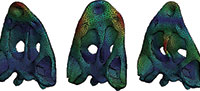
Some inner regions as the air space between the vomer and the skull roof bones, the endocranial area and the inner part of the cultriform process were reconstructed based in the descriptions by (Bystrow and Efremov, 1940; Dutuit, 1976; Schoch, 2002). These issues were done using the CAD interface of the Finite Element Package ANSYS 14.5 (Figure 1).
A spider web of beams is built to connect the areas of boundary conditions or forces with the interface point where the force or the boundary condition will be applied to ensure that the modal reduction method can be carried out successfully. In this case, a spider web of beam elements is created between the skull and the fixed boundary conditions in the spine allowing for the movement of the neck as described by (Hohn-Schulte et al., 2013), this justifies the location of the rotation’s center in the model.
This method is recommended because force can be distributed over an area without the creation of mass elements and moments are properly transmitted from the interface point to the structure. It also simplifies the multibody modeling.
Description of the Finite Element Model
 The skull was analyzed to evaluate the stress state using the Finite Elements Method Package ANSYS® 14.5 for Windows 7 (64-bit system) in a Dell Precision™ Workstation T7600 with 32 GB (4X8GB) and 1600 MHz. Linear, elastic and homogeneous properties were assumed for the cortical bone of the skull, using the following values: E (Young’s modulus) 6.65 GPa and v (Poisson’s ratio) 0.35, based on the frontal and prefrontal bones from Crocodylus (Currey, 1987). A simple mesh of 12880 nodes and 54337 linear tetrahedral elements of four nodes were created with beam elements in the spider web connecting the spine with the skull.
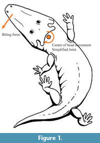
An arbitrary force of 800 N is applied in the anterior part of the skull simulating different feeding movements according the three different cases described in Figure 2. Although this value is arbitrary, taking into account that most of the ultimate strengths in bones are between 100 and 200 MPa (Currey, 1990), this force fits the Von Mises Stress values around this maximum values giving the examples more realistic results. The skull is fixed in the condyle following the two cases described below with or without a web of beams acting as boundary conditions.
Description of the Multibody Model
The multibody model was created in the MSC Software ADAMS® for Windows XP (64-bit system), and it is based on the input created by modal analysis performed in ANSYS. The goal of modal analysis in structural mechanics is to determine the mode shapes and corresponding frequencies of a structure during constrained vibration and deformation modes due to unit displacements (Bampton and Craig, 1968). It is common to use FEA to perform this analysis because when using FEA, the object being analyzed can have an arbitrary shape, as a vertebrate skull. The data between the software are transferred only once. In case of ADAMS multibody package coupling is done through the so-called Modal Neutral File (MNF), which is a proprietary file format that allows porting the flexible body description from finite element software to Adams. The multibody model consists of one flexible body that represents the skull; fixed joint connecting the head to the ground; and a three component force that can be adjusted to produce the different test cases. As the simulation starts, the force is linearly ramped from zero to the final value (800 N) within 0.5 seconds, to represent quasi-static force application and avoid the need for the initial static optimization. Dynamic simulation solver is used with standard integrator settings (integrator: GSTIFF, formulation: I3, error norm: 0.001, maximum iterations allowed for convergence: 10).
Test Procedure
Two different problems were solved. One, where the constraints are applied directly to the surface nodes of the model (cases A), and the second one, where an auxiliary constrain node is created and connected with the nodes to be fixed by rigid massless beams (cases B). In the first approach, the fixed boundary conditions are applied in the skull whereas in the second, the interface points in the spine are fixed. For each problem three cases are solved modifying the direction of the applied force in the three principal axes as shown in Figure 2. For each case, first, a static structural analysis is done using FEA and the second, different solutions are obtained in function of the number of modes used: 30, 50, 100 and 200 using the FMSD.It is important to state that case A was presented just to visualize the caveats of modeling boundary conditions, while case B is the correct modeling technique of an FMSD model. The elapsed time spent for ANSYS to solve the static structural FEA is 30 seconds for each case. On the other hand, the elapsed time spent for ANSYS and ADAMS to solve the FMSD range from 3 minutes (30 modes) to 16 minutes (200 modes). It has to be noted that in the case of FMSD 3 seconds of motion with 0.01 s time step are solved in the given time, which gives only 3.2 s per time step compared to 30 seconds of FE simulation time.
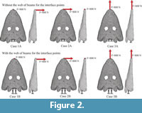
 The Von Mises stress results were evaluated at nine different nodes scattered on the surface of the skull, which are indicated in Figure 3. The stress values computed by the flexible multibody approach were compared to the results of the corresponding finite element analysis. To assure that the nodal values compared between models solved in the FEA and in the FMSD are exactly the same and that the models are compatible, when the MNF is created, the numeration of the nodes is checked, and the boundary conditions and the forces are applied at the same nodes. We assume the finite element analysis here as the reference data just to compare different modeling techniques, but it has to be noted that in order to truly validate any numerical model with respect to reality, experimental measurements should be used.
RESULTS
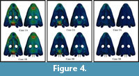 Static analysis with Finite Element Analysis was conducted. Two test cases were evaluated, with direct application of constraints on the surface nodes of the model (test case A), and with the massless beams connecting the surface nodes to the constrain nodes (test case B). Figure 4 shows the Von Mises stress distribution in the skull obtained for the static analysis in FEA in the cases described in Figure 2 with the web of beams (case B) and without (case A). The numerical results are recorded in nodes from the nine different locations in the skull in order to compare the results obtained from the FMSD with the ones obtained in FEA. Numerical results for test cases A and B are presented in the Table S1 and Table S2 of the supplementary information, respectively. The Von Mises criterion is an isotropic criterion traditionally used to predict the yielding of ductile materials such as metals. Bone could be considered brittle (Doblaré et al., 2004) or ductile (Dumont et al., 2009) but, according to Doblaré et al. (2004) when isotropic material properties are used in cortical bone, the Von Mises criterion may be the most accurate for predicting fracture location regardless of its consideration.
The selection of these nine nodes is taking into account that nodes close to the place where the fixed boundary conditions are applied and nodes close to the point where the force is applied are not selected to avoid results affected by the artificial noise in the Von Mises stress values. The artificial noise is a numerical singularity, which appears close to some boundary conditions, punctual forces and sharp angles in the geometry. It is well-known in the field of FEA and shouldn’t be considered in the analysis of the stress results of the models (Marcé-Nogué et al., in press). The resolution of the static analysis helps in the selection of those nine points.
Dynamic Analysis with Flexible Multibody System Analysis
 Two test cases were evaluated, with direct application of constraints on the surface nodes of the model (test case A) and with the massless beams connecting the surface nodes to the constrain nodes (test case B).
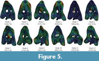
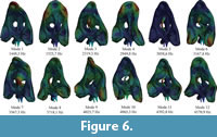
For solving the FMSD, firstly 200 modes of the skull have been obtained from a modal analysis in both cases A (without the web of beams) and case B (with the web of beams). Figure 5 and Figure 6 show the first 12 modes of both cases and Table S3 and Table S4 in the supplementary information show the values of the frequencies for the 200 modes for test case A and B, respectively. The first modes contribute the most to the total strain energy of the model.
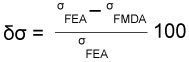
To compare the different results of stress obtained when different numbers of modes are used, an error is evaluated between FEA and FMSD results. The percent error between the Von Mises stress obtained in the FEA and the FMSD is evaluated according to equation 1 where the numerical results of von Mises stress obtained using FEA (σFEA in the equation) and FMSD (σFMDA in equation) can be checked in Table S1 and Table S2 of the supplementary information.
|
|
(1) |
 The stress results error is presented in Table 1 for the case where the boundary conditions were applied directly on the nodes. Results for cases with massless rigid beam connections are presented in Table 2. The mean of the error value for the nine cases is calculated for all the cases and also shown in the table when different numbers of modes are used in the FMSD.
Finally a summary of the mean error for each test case versus the number of deformation modes used is presented in Figure 7. It shows that for the case 1A, 2A and 3A, where the constraint are applied directly to the surface nodes of the model without the spider-web beams, the overall error is higher than, 70% in case 1A, 55% in case 2A and 20% in case 3A. And the tendency of this error does not vary considerably when the number of deformation modes used in 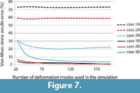 Craig-Bampton is changed. This incorrect result agrees with the fact that case A is not usually the correct way to model an FMSD problem and was presented as a warning for the readers. On the other hand, for the cases where an auxiliary constrain node is created and connected with the nodes to be fixed by rigid massless beams (the right way to model an FMSD problem), the overall error decreases to values lower than 5% when the number of deformation modes increases.
It must be taken into account that when describing the overall accuracy, dealing with single node values does not give the clear picture of the method accuracy. Therefore, average values are used in comparisons. Differences that were larger than the average occurred on nodes which are subjected to very low stress, thus numerical error has greater influence than the stress result itself here.
DISCUSSION
The methodology presented herein was not used before to study the feeding mechanism of vertebrate structures. It is important to differentiate the FMSD, which couples the equations of the MSD and the FEA during the simulation from the other excellent approaches that can be found in the literature. Firstly, in Curtis et al. (2009, 2010a), Bates and Falkingham (2012) and Snively et al. (2013) only the MSD equations are used to determine the forces that are acting in the model without any interaction with FEA and secondly, in Moazen et al. (2008a) and Curtis et al. (2011) there is a combination between MSD and FEA but they are not coupled during the simulation. Uncoupled analysis does not account for strains being a result of dynamics response of a flexible object. Also uncoupled analysis in this case means remarkably higher computational expense for evaluation of the stresses for each single time step instead the coupled analysis proposed herein.
Multibody dynamics as well as its sibling called flexible multibody dynamics are methods that aim to make transient analysis of systems’ dynamics. Of course, it is possible to use those methods in quasi-static analyses as it has been done in the past in biological research, but then the full potential of the method cannot be used. The frequently used method, referred to as linear theory of elastodynamics, is based on rigid multibody simulation followed by finite element analysis. The drawback of the methodology is that to assess stresses through the whole simulation cycle, one has to perform many finite element analyses. In case of using flexible multibody dynamics, dynamic simulation output contains stresses for each single time step of the simulation. This is why we believe this methodology has more potential than the widely used theory of elastodynamics.
In this case example, first the MSD is solved to transfer the forces to the FEA and study the structural problem. Such an approach in this particular case does not create significant error; however, it assumes that the deformation of the structure does not affect the dynamical behavior, which can be questioned. In other words, even though the structure is to some extent flexible, it is considered rigid, and the flexibility is only used to assess internal forces and deformation.
In case of the systems which exhibit relatively large flexibility, the goal of the floating frame of reference formulation is to account for deflections in the dynamic response of the system (Shabana, 1997). There is, however, no obstacle in using floating frame of reference formulation for relatively stiff systems like bones. Rigid multibody dynamics does not allow accounting for internal loads like stresses and strains. Accounting for flexibility is just a way to enable internal load estimation in the multibody approach. Floating frame of reference formulation is one of such approaches that is very efficient, thus it allows one to study stresses within bones, induced during the chewing process. Achieving the same effect using only a finite element approach would require a much higher computational power and memory.
Nonetheless, using the new methodology FMSD, the results summarised in Figure 7, clearly indicate that the number of deformation modes has a remarkable effect on the results accuracy. As it could be expected based on the linear theory of elasticity (Slaughter, 2002), the higher the number of deformation modes used, the more accurate the results. However, using 100 deformation modes already lowers the maximum error below 6%. The tradeoff between accuracy and speed of this method in biomechanical studies was presented in an earlier conference paper (Kłodowski et. al., 2011).
Application of boundary constrains has the most significant effect on the results. For the same conditions, the difference between direct and through beams constraint application can account for as much as 72.24%. In the case of modal reduction, direct application of constraints (such as case A) will result on their penetration further through the model, and this is what causes large discrepancies between modally reduced models with directly applied constraints and full finite element models. Indirect constraints applications, however, are proven to solve the problem (case B).
Load direction also has an effect on the results accuracy. The longitude direction, which results in tension of the specimen, produces significantly less accurate results than loads causing bending. Interestingly, the bending stiffness does not affect the accuracy in any significant manner. It can be seen comparing bending in the test cases 1 and 2, where the bending stiffness differs significantly, while the error difference is minor.
Biting results in dominating bending load in the jaw as well as in the skull, thus for such application, the flexible multibody approach seems to be a good tool. By using FMSD, the whole chewing process could be studied not limiting the research to sole biting. The way boundary conditions are applied in the finite element model has a dramatic effect on the modal analysis results. Therefore it is advised to use massless beams as connectors of the surface nodes to the constraint nodes, to enhance accuracy of the simulation. In the current study, the error level using direct constrains on surface nodes varied between 20% and 75%. Using intermediate beam elements to apply boundary constrains reduced the error to the range of 0.86% to 30% depending on the number of deformation modes used. In such constrain configurations; use of at least 100 deformation modes restricts the error to maximally 5.58%. This conclusion opens a wide range of possible new studies in the field of paleontology and computational mechanics to improve the knowledge in this area about feeding mechanisms.
The approximation of stresses and strains in this method is independent of source of loading. For test purposes, we have conducted a simulation with constant force value, but the solver utilized was set for dynamic simulation and actually a couple of seconds of constant load was simulated. Therefore, reasonable approximation of stresses is also to be expected from a simulation where the external force is time dependent and, consequently, the analysis is dynamic.
Large differences between finite element stress values and FMSD stresses for a low number of deformation modes are a result of approximation of the stresses within the skull. It has to be noted that the far location of the node with respect to boundary conditions does not guarantee automatically high accuracy of the approximated stress results; however, the nodes in direct proximity to the boundary conditions are affected more by the constrain conditions than nodes located further from the constrain application nodes. Therefore, modally reduced model should always be verified with respect to the original FE model to determine if the number of deformation modes and boundary conditions applied are providing accurate enough stress approximation.
As in any modeling technique based on reduction of the models, the results are approximated as compared to the full scale model. This means that, using a low number of deformation modes can lead to significant errors. This behavior is analogical function approximation. For simple functions low order polynomials will work great, but for complex functions, higher order polynomials or more complex functions have to be used, otherwise the errors will be significant. Thus, care must be taken to choose a sufficient number of modes (that are a sort of approximation function) to represent the original model with required accuracy.
CONCLUSIONS
Uncoupled analysis of MDA and FEA have been used before to estimate forces acting on a skull and then applied to a Finite Element Model of this same skull to obtain patterns of strain and stress across it (Moazen et al., 2008a, 2008b, 2009a, 2009b; Curtis et al. 2008, 2010a, 2010b, 2011). Those results have been combined with knowledge of evolutionary paths to develop hypotheses regarding the genetic and epigenetic factors that shape the skeleton or the feeding mechanism in vertebrate structures.
In the work presented herein, a coupling of MDA and FEA was presented for a flexible multibody approach. According to the results presented herein for the comparison of FMSD and a static structural FEA, the use of this new and challenging approach is also recommended for the study of feeding mechanisms in vertebrate structures such as the skull of an Edingerella madagascariensis when a dynamic analysis is to be tested.
ACKNOWLEDGEMENTS
The authors want to thank J.S. Steyer and R. Allain (Muséum National d'Histoire Naturelle, Paris) for the loan, Hospital Mútua de Terrassa for the CT scanning of Edingerella and J. Fortuny (Institut Català de Paleontologia, Sabadell) for their comments in order to improve the content of the manuscript. This research has been supported by project CGL 2011-30069-C02-01 of the Ministerio de Ciencia e Innovación of the Spanish government. Comments of two anonymous reviewers greatly improved the previous version of this manuscript.
REFERENCES
Abel, R., Laurini, C., and Richter, M. 2012. A palaeobiologist’s guide to “virtual”micro-CT preparation. Palaeontologia Electronica, Vol. 15, Issue 2;6T,17p;
palaeo-electronica.org/content/issue-2-2012-technical-articles/233-micro-ct-workflow.
Al Nazer, R., Klodowski, A., Rantalainen, T., Heinonen, A., Sievänen, H., and Mikkola, A. 2011. A full body musculoskeletal model based on flexible multibody simulation approach utilised in bone strain analysis during human locomotion. Computer Methods in Biomechanics and Biomedical Engineering, 14(6):573-579.
Ambrósio, J. and Gonçalves, J. 2001. Complex flexible multibody systems with application to vehicle dynamics. Multibody System Dynamics, 6:163-182.
Bampton, M.C.C. and Craig, Jr., R.R. 1968. Coupling of substructures for dynamic analyses. American Institute of Aeronautics and Astronautics Journal, 6:1313-1319.
Bates, K.T. and Falkingham, P.L. 2012. Estimating maximum bite performance in Tyrannosaurus rex using multi-body dynamics. Biology Letters, 8:660-664.
Bystrow A.P. and Efremov J.A. 1940. Benthosuchus sushkini Efr., a labyrinthodont from the Eotriassic of Sharzhenga River. Travaux de l'Institut Paleontologique, Academy des Sciences de l'URSS 10:1-152.
Currey, J.D. 1987. The evolution of the mechanical properties of amniote bone. Journal of Biomechanics, 20:1035-1044.
Currey, J.D. 1990. Physical characteristics affecting the tensile failure properties of compact bone. Journal of Biomechanics, 23:837-844.
Curtis, N. 2011. Craniofacial biomechanics: an overview of recent multibody modelling studies. Journal of Anatomy, 218:16-25.
Curtis, N., Jones, M.E.H., Evans, S.E., O’Higgins, P., and Fagan, M. J. 2009. Visualising muscle anatomy using three-dimensional computer models-an example using the head and neck muscles of Sphenodon. Palaeontologia Electronica, Vol. 12, Issue 3; 7T: 18p; palaeo-electronica.org/2009_3/194/index.html
Curtis, N., Jones, M.E.H., Evans, S.E., Shi, J., O’Higgins, P., and Fagan, M.J. 2010a. Predicting muscle activation patterns from motion and anatomy: modelling the skull of Sphenodon (Diapsida: Rhynchocephalia). Journal of the Royal Society, Interface / the Royal Society, 7(42):153-160.
Curtis, N., Jones, M.E.H., Lappin, A.K., Evans, S.E., O’Higgins, P., and Fagan, M. J. 2010b. Comparison between in vivo and theoretical bite performance: using multi-body modelling to predict muscle and bite forces in a reptile skull. Journal of Biomechanics , 43:2804-2809.
Curtis, N., Jones, M.E.H., Shi, J., O’Higgins, P., Evans, S.E., and Fagan, M. J. 2011. Functional relationship between skull form and feeding mechanics in Sphenodon, and implications for diapsid skull development. PloS one , 6:e29804.
Curtis, N., Kupczik, K., O’Higgins, P., Moazen, M., and Fagan, M. J. 2008. Predicting skull loading: applying multibody dynamics analysis to a macaque skull. Anatomical Record, 291:491-501.
Doblaré, M., Garcı́a, J.M., and Gómez, M.J. 2004. Modelling bone tissue fracture and healing: a review*1. Engineering Fracture Mechanics, 71:1809-1840.
Dumont, E.R., Grosse, I.R., and Slater, G.J. 2009. Requirements for comparing the performance of finite element models of biological structures. Journal of Theoretical Biology, 256:96-103.
Dutuit, J.M. 1976 Introduction à l’étude paléontologique du Trias continental marocain : description des premiers Stégocéphales recueillis dans le couloir d'Argana (Atlas occidental). Éditions du Muséum, Paris.
Eringen, A.C. and Șuhubi, E.S. 1974. Elastodynamics: Finite Motions, Academic Press, New York-London.
Fortuny, J., Marcé-Nogué, J., de Esteban-Trivigno, S., Gil, L., and Galobart, A. 2011. Temnospondyli bite club: ecomorphological patterns of the most diverse group of early tetrapods. Journal of Evolutionary Biology, 24:2040-2054.
Fortuny, J., Marcé-Nogué, J., Gil, L., and Galobart, A. 2012. Skull mechanics and the evolutionary patterns of the otic notch closure in capitosaurs (Amphibia: Temnospondyli). Anatomical Record, 295:1134-1146.
Fortuny, J., Marcé-Nogué, J., and Steyer, S. 2012. 3D Finite Element Analysis of a Capitosaurian Skull (Temnospondyli) from the Triassic of Madagascar. Journal of Vertebrate Paleontology, 32:96.
Gröning, F., Jones, M.E.H., Curtis, N., Herrel, A., O’Higgins, P., Evans, S.E., and Fagan, M. J. 2013. The importance of accurate muscle modelling for biomechanical analyses: a case study with a lizard skull. Journal of the Royal Society, Interface / the Royal Society, 10:0130216.
Hohn-Schulte, B., Preuschoft, H., Witzel, U., and Distler-Hoffmann, C. 2013. Biomechanics and functional preconditions for terrestrial lifestyle in basal tetrapods, with special consideration of Tiktaalik roseae. Historical Biology, 25:167-181.
Khulief, Y. 2001. Dynamic response calculation of spatial elastic multibody systems with high-frequency excitation. Multibody System Dynamics, 5:55-78.
Klodowski, A., Rantalainen, T., Mikkola, A., Dastidar, P., Heinonen, A., and Sievänen, H. 2009. A dynamic simulation of a human gait using the hybrid muscle model and a QCT-Based flexible tibia. In Proceedings of the ASME 2009 International Design Engineering Technical Conferences and Computers and Information in Engineering Conference. ASME:1-10.
Kłodowski, A., Valkeapää, A., and Mikkola, A. 2011. Craig-Bampton Modal Reduction Applied to Human Tibia Tradeoff Between Accuracy and Speed. ASME International Mechanical Engineering Congress and Exposition, Dener, Colorado, USA, Paper No. IMECE2011-63618:483-487.
Kłodowski, A., Valkeapää, A., and Mikkola, A. 2012. Pilot study on proximal femur strains during locomotion and fall-down scenario. Multibody System Dynamics, 28:239-256.
Maganuco, S. 2009. An exquisite specimen of Edingerella madagascariensis (Temnospondyli) from the Lower Triassic of NW Madagascar: cranial anatomy, phylogeny, and and restorations. Memorie della Società Italiana di Scienze Naturali e del Museo Civico di Storia Naturale di Milano, 36:1-72.
Marcé-Nogué, J., Fortuny, J., Gil, L., and Galobart, A. 2011. Using Reverse Engineering to Reconstruct Tetrapod Skulls and Analyse Its Feeding Behaviour. Proceedings of the Thirteenth International Conference on Civil, Structural and Environmental Engineering Computing. Civil-Comp Press, Stirlingshire, UK, Paper 237.
Marcé-Nogué, J., Fortuny, J., Gil, L., and Sánchez, M. In press. Improving mesh generation in Finite Element Analysis for functional morphology approaches. Spanish Journal of Palaeontology (Accepted October 2013).
Moazen, M., Curtis, N., Evans, S.E., O’Higgins, P., and Fagan, M. J. 2008a. Combined finite element and multibody dynamics analysis of biting in a Uromastyx hardwickii lizard skull. Journal of Anatomy, 213:499-508.
Moazen, M., Curtis, N., Evans, S.E., O’Higgins, P., and Fagan, M. J. 2008b. Rigid-body analysis of a lizard skull: modelling the skull of Uromastyx hardwickii. Journal of Biomechanics, 41:1274-1280.
Moazen, M., Curtis, N., O’Higgins, P., Evans, S.E., and Fagan, M. J. 2009b. Biomechanical assessment of evolutionary changes in the lepidosaurian skull. Proceedings of the National Academy of Sciences of the United States of America, 106:8273-8277.
Moazen, M., Curtis, N., O’Higgins, P., Jones, M.E.H., Evans, S.E., and Fagan, M. J. 2009a. Assessment of the role of sutures in a lizard skull: a computer modelling study. Proceedings of the Royal Society B, 276(1654):39-46.
Rayfield, E.J. 2007. Finite element analysis and understanding the biomechanics and evolution of living and fossil organisms. Annual Review of Earth and Planetary Sciences, 35:541-576.
Schoch, R.R. 2002. The neurocranium of the stereospondyl Mastodonsaurus giganteus . Palaeontology, 45:627-645.
Shabana, A. 1997. Flexible multibody dynamics: review of past and recent developments. Multibody System Dynamics, 1:189-222.
Slaughter, W. 2002. The Linearized Theory of Elasticity, Birkhäuser, Boston .
Snively, E., Cotton, J.R., Ridgely, R., and Witmer, L.M. 2013. Multibody dynamics model of head and neck function in Allosaurus (Dinosauria, Theropoda). Palaeontologia Electronica, Vol. 16, Issue 2; 11A 29p; palaeo-electronica.org/content/2013/389-allosaurus-feeding.
Walmsley, C.W., McCurry, M.R., Clausen, P.D., and McHenry, C.R. 2013. Beware the black box: investigating the sensitivity of FEA simulations to modelling factors in comparative biomechanics. PeerJ, 1:e204.
Wasfy, T.M. and Noor, A.K. 2003. Computational strategies for flexible multibody systems. Applied Mechanics Reviews, 56(6):553-613.
Zhu, C.X., Liu, Y.X., Cai, G.Q., and Zhu, L.D. 2008. Dynamics Simulation Analysis of Flexible Multibody of Parallel Robot. Applied Mechanics and Materials, 10-12:647-651.
Zienkiewicz, O. 1971. The Finite Element Method in Engineering Science, McGraw-Hill, Boston.
