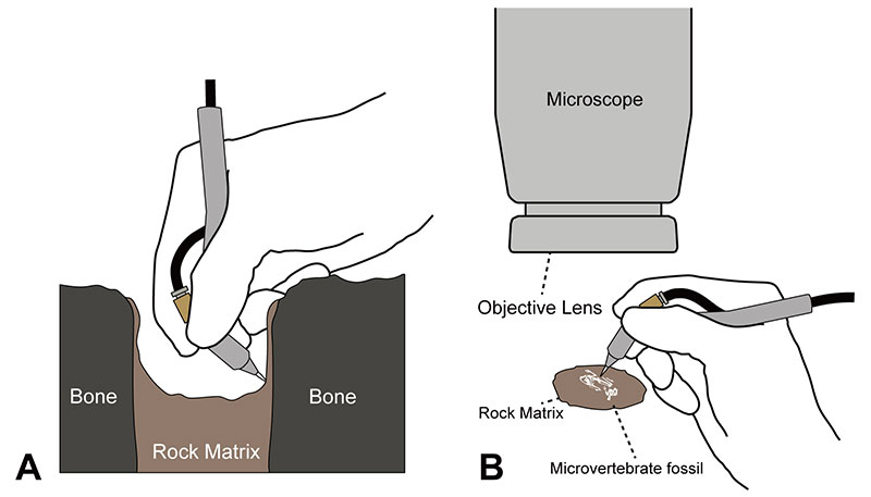
FIGURE 1. Usage example of a conventional pen-shaped pneumatic air scribe. A. Fossil preparation inside of the deep cavity. Note that preparators are required to hold the air scribe at an awkward angle when they try to prepare a hard-to-reach area. B. Micropreparation using the pen-shaped air scribe. The handle of the air scribe could be caught on the rim of the objective lens.
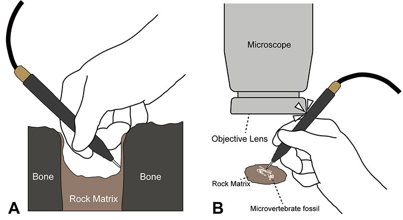
FIGURE 2. List of the components for one Wada air scribe and two forms of the handle. The "M" designation for metric screws indicates the outer diameter of the screw thread in mm.
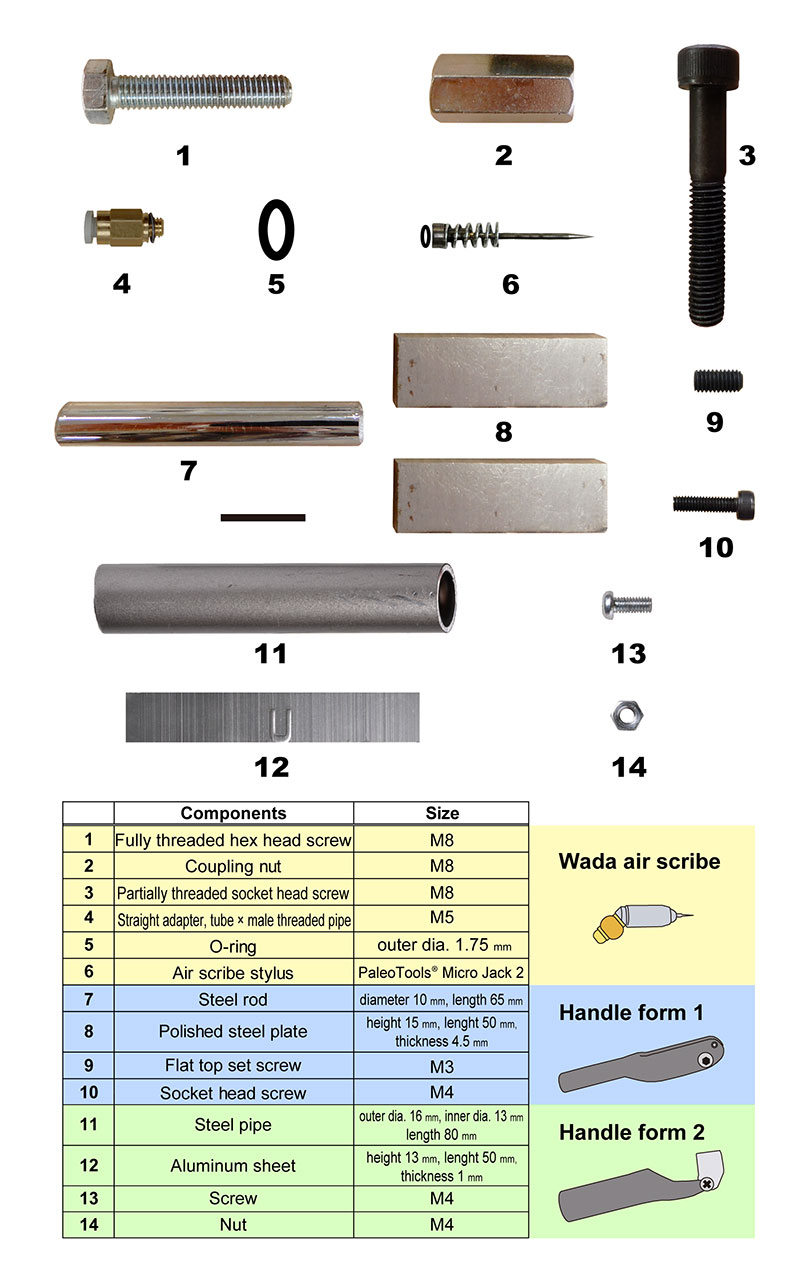
FIGURE 3. The junction (A-E), cylinder (F-J), and bushing (K-O) in right lateral (A, B, C, F, G, H, K, L, and M), back (D), and front (I and N) views. The component numbers correspond to those of Figure 2. A, one-fifth from the screw head of a fully threaded hex screw; B, the junction; C, diagram of the junction; D, the junction; E, cross section of the junction; F, a coupling nut; G, the cylinder; H, diagram of the cylinder; I, the cylinder; J, cross section of the cylinder; K, middle part of a partially threaded socket head screw; L, the bushing; M, diagram of the bushing highlighting the stem and an exhaust hole; N, the bushing; O, cross section of the bushing.
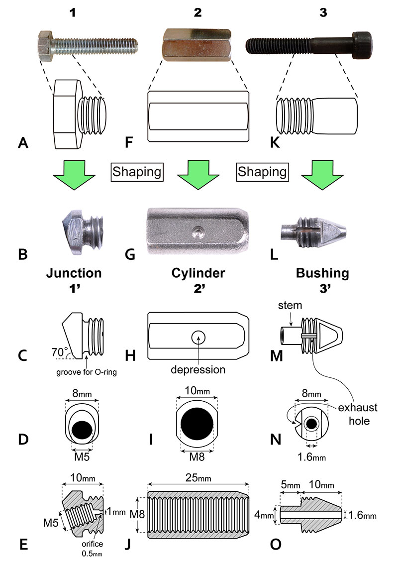
FIGURE 4. The assembly drawing of the stylus, spring, and bushing. Note that the distance between the bushing and the base of the stylus must be more than 1 mm.

FIGURE 5. The Wada air scribe. A, the structure of the Wada air scribe. The component numbers correspond to those in the Figure 2; B, diagram of the Wada air scribe in lateral view; C, cross section of the Wada air scribe in lateral view.
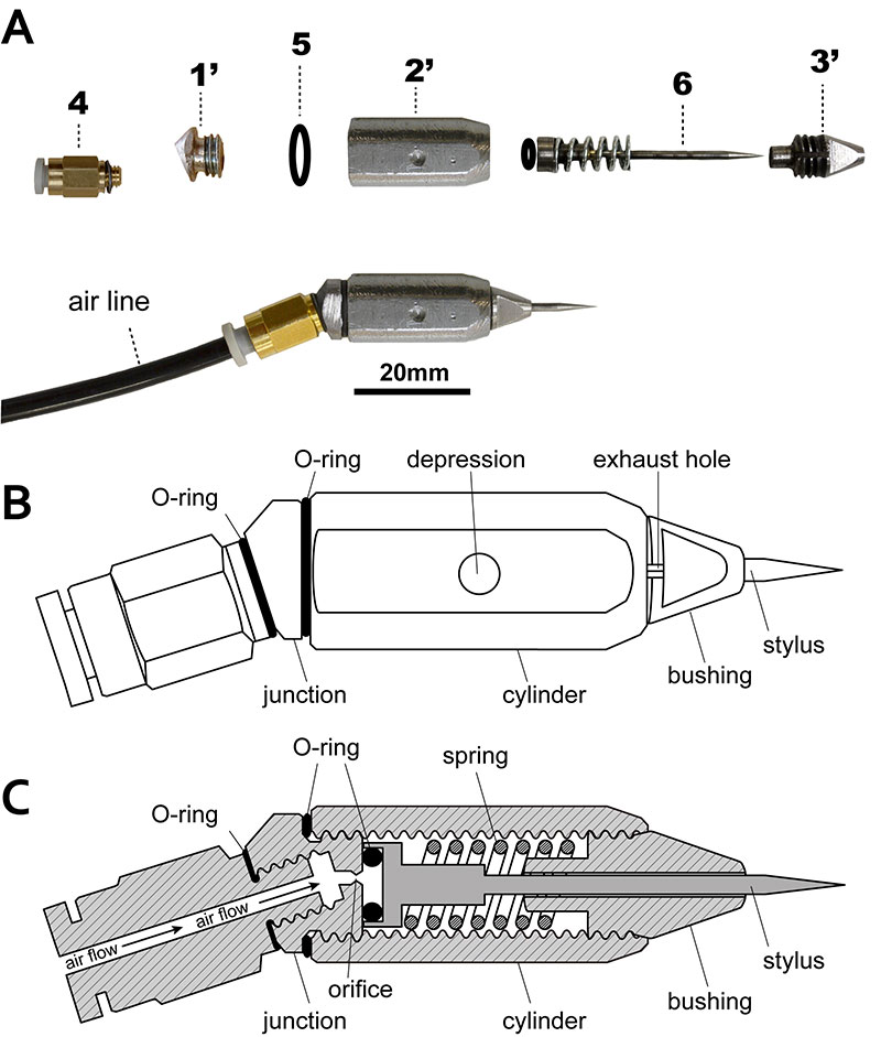
FIGURE 6. The handle form 1. A, production process. The component numbers correspond to those in Figure 2; B, the handle in right lateral view; C, the handle in top view; D, the handle with the socket head screw (M4) in bottom view; E, the handle in left lateral view.

FIGURE 7. The handle form 2. A, production process of the support rod; B, production process of the body holder; C, the support rod in right lateral view; D, the support rod in top view; E. the support rod in bottom view; F, the support rod in front view; G, the body holder in right lateral view; H, the body holder in front view. The component numbers correspond to those in Figure 2.

FIGURE 8. The assembly drawing of the Wada air scribe and the handle form 1 (A-C) and 2 (D-F). A, insert the air scribe between the left and right arm; B, angle adjustment of the Wada air scribe; C, the Wada air scribe with the handle form 1 in right lateral view; D, insert the air scribe into the body holder and attach them to the support rod; E, angle adjustment of the Wada air scribe; F, the Wada air scribe with the handle form 2.

FIGURE 9. The Wada air scribe with handle forms 1 (A-C) and 2 (D-F) at a straight angle (0 degrees) (A and D) and a right angle (90 degrees) (B and D), respectively. Using a closed-cell polyurethane foam sleeve cover to encase the handles can effectively reduce the impact on the hand (C and F).

FIGURE 10. Comparison between the commercially available air scribe and the Wada air scribes. A, a pen-shaped air scribe (Micro Jack 2 from PaleoTools®); B, the Wada air scribe.
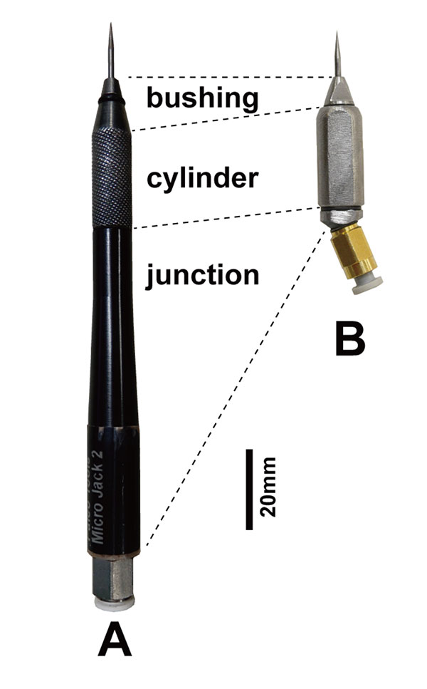
FIGURE 11. Usage example of the Wada air scribe. A, fossil preparation inside of the deep cavity; B, preparation under a microscope using the Wada air scribe.
