|
|
|
RESULTSReconstructed topography of pneumatic diverticula in sauropod necks
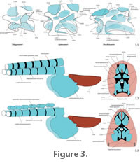
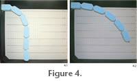
Size and depth of the pneumatic fossae and foramina in the lateral surface of the vertebral bodies, and comparisons with extant birds indicate large LVDv along the entire lateral surface of the cervical centra (Figure 3). The LVDv passed through the intertransversal foramina, forming a lateral vertebral pneumatic diverticula system similar to the canalis intertransversarius in birds (Müller 1908; Landolt and Zweers 1985). The lumen of the intertransversal foramina was most likely completely occupied by pneumatic diverticula, therefore the diameters of these foramina hint to the cross-section of the whole unit of LVDv. The LVDv were laterally bounded by the cervical ribs, connective tissue, and lateral epaxial and laterocostal cervical muscles, which inserted on the diapophyses and cervical ribs (Wedel and Sanders 2002; Schwarz et al. 2007). Like in birds (Müller 1908; Duncker 1971; O'Connor 2006), the pneumatic diverticula of sauropods were most probably connected with each other by a network of pneumatic ducts, although fossil evidence for pneumatic ducts is rare (Wedel et al. 2000). Pneumatic fossae in the external vertebral surface of many sauropod taxa, such as Diplodocus, Apatosaurus, Barosaurus, Camarasaurus or Brachiosaurus, are internally divided into subfossae, which indicates a segmentation of the respective pneumatic diverticula into subunits (Wilson 1999; Wedel 2005). Most likely, these diverticula anastomozed at least occasionally with one another, similar to birds (O'Connor 2006). It is likely that corresponding to extant birds, adjacent pneumatic diverticula were bundled together to "aggregates of narrow tubes rather than large, simple sacs" (Wedel 2003a, figure 5 caption). Rare pneumatic foramina and depressions on the medial surface of the metapophyses and within the postspinal cavity of the cervical vertebrae indicate that SVDv filled the gap between these metapophyses and the postspinal cavity, respectively (Figure 3.2-3.3) (Schwarz and Fritsch 2006; Schwarz et al. 2007). In sauropods with single neural spines in the neck, pneumatic diverticula formed large evulsions in the interarticular gaps, as is seen in extant birds (Müller 1908; Britt 1993; O'Connor 2001; Wedel 2003a; O'Connor 2006). Median tuberosities within the postspinal cavity and between the metapophyses of bifurcate neural spines provide osteological evidence for large elastic ligaments inserting cranially and caudally on the neural spines of sauropods (Tsuihiji 2004; Schwarz et al. 2007). Therefore, pneumatic diverticula between the metapophyses and within the postspinal cavity must have been medially in direct contact with these elastic ligaments, proliferating around the latter (Figure 3.2-3.3). Additionally, thin laminae on the cranial and caudal margin of the metapophyses, and the well-developed postzygapophyseal laminae suggest the presence of a paired interspinal septum like in extant Crocodylia (Frey 1988a; Schwarz et al. 2007). Between single neural spines, the left and right sheet of the interspinal septum probably enclosed the elastic ligament and the SVDv, which both filled also the postspinal fossa (Schwarz and Fritsch 2006; Schwarz et al. 2007). In bifurcate neural spines, the interspinal septum probably adjoined the SVDv around the elastic ligaments and dorsally contacted the supraspinal ligament. Such an arrangement of spinal ligament sheaths would have provided a hose-like envelope for the dorsal pneumatic diverticula. The width of the area between the metapophyses indicates the volume of the SVDv including their ligamentary envelope. According to the distribution of pneumatic diverticula along the neck of sauropods, a tripartite arrangement can be distinguished from a dual one (Figure 3). Sauropods with a tripartite arrangement of pneumatic diverticula have bifurcate neural spines in at least half the cervical vertebrae, such as Apatosaurus, Diplodocus, Dicraeosaurus or Amargasaurus. In the area of bifurcate neural spines, the entity of SVDv formed a dorsal median pneumatic canal around the elastic ligaments (Figure 3.2). Additionally, a pair of LVDv units at the vertebral centra, assembled in an intertransversar canal, would have been present. In sauropods with a dual arrangement of pneumatic diverticula, bifurcate neural spines occurred in less than half of the cervical vertebrae, like in Camarasaurus, or were completely missing like in Mamenchisaurus or Euhelopus. In the first case, single SVDv formed a dorsal pneumatic canal in the caudal region of the neck only (Figure 3.3). In the second case, SVDv filled the interarticular space and the postspinal cavity. Similar to the tripartite arrangement, the LVDv formed a paired, voluminous, hose-like intertransversar canal. Results of the Experiment - Pneumatic Stabilization of a Chain BeamThe experiment was carried out with those configurations of balloons corresponding to the arrangement of pneumatic diverticula reconstructed for sauropod necks. Each experimental approach (E1-E8) followed a specific question that is outlined below. In the following description, proximal refers to the end of the chain fixed at the pivot board, whereas distal refers to the opposite end bearing the plastic cup with iron powder. The sagging index (si; in mm) indicates the holding point of the distal end of the chain beam aboveground in a vertical plane. The bending index (bi; in mm) is the dislocation of the distal end of the chain beam from the straight line in a horizontal plane. E1: Calibration of the unbraced chain beam.Objective: What is the maximum si of the system without pneumatic bodies and with other bracing elements?
E2: One median ventral pneumatic tubeObjective 1: What is the bracing and deformation effect of one median ventral pneumatic tube?
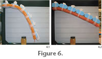
Objective 2: How does the median ventral pneumatic tube influence the load capacity of the chain beam and what effect has a pressure increase to the load capacity? An empty cup was attached to the distal end of the chain beam and filled with iron powder until siE1 was reached. No ventral intersegmental wedges were used. At a pressure of 0.15 bar, 45 g of iron powder was necessary to produce siE1, which is 122.5% of the weight of the chain beam itself. At a pressure of 0.25 bar, 230 g of iron powder was necessary to deflect the chain to siE1 (Figure 5.3). This corresponds to 215% of the weight of the chain beam. As a result, a pressure increase of 0.1 bar only increased the load capacity of the system by five times. In both load cases, the chain beam tended to twist around its long axis due to torque moments. E3: One pair of ventral or lateral pneumatic tubesObjective 1: What is the bracing effect with a pair of lateral or ventral pneumatic bodies respectively?
Objective 2: How does the configuration influence the load capacity of the chain beam? An empty cup was attached to the distal end of the chain beam and filled with iron powder until the curvature siE1 was reached. At a pressure of 0.15 bar, 80g of iron powder were needed to reach siE1, corresponding to 140% of the weight of the chain beam. E4: One pair of ventral and a median dorsal pneumatic tubeObjective 1: What is the bracing effect with two ventral and one dorsal pneumatic body?
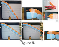
Objective 2: How does the configuration influence the load capacity of the chain beam? An empty cup was attached to the distal end of the chain beam and filled with iron powder until siE1 was reached. The pressure of the balloons was 0.15 bar, and no intersegmental wedge was inserted. With this arrangement, 54 g of iron powder were necessary to achieve siE1 (Figure 7.3), corresponding to 127% of the inertial weight of the chain beam. Inserting an intersegmental wedge ventrally between the two proximal segments increased the load capacity to bear 136 g until reaching siE1, which is 168% of the inertial weight of the chain beam. E5: One median dorsal pneumatic tubeObjective 1: What is the bracing effect with one dorsal pneumatic body?
Objective 2: How does the configuration influence the load capacity of the chain beam and what influence has the basal pivot? An empty cup was attached to the distal end of the chain beam and filled with iron powder until siE1 was reached. In the arrangement with one ventral intersegmental wedge and the proximally unfixed balloon with a pressure 0.15 bar, 34 g of iron powder were necessary to achieve siE1. This corresponds to 117% of the intrinsic weight of the chain beam. In the arrangement with one ventral intersegmental wedge and an additional proximal fixation of the balloon, 54 g of iron powder were necessary to achieve siE1. This was 127% of the intrinsic weight of the chain beam. At this load, the balloon buckled proximally. E6: One median dorsal or ventral pneumatic tube fixed to the segmentsObjective: What is the influence of a segmentally fixed median pneumatic body on the bracing of the chain beam?
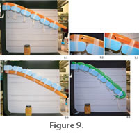
In a second test, one balloon was tied to the ventral side of the chain beam with gauze bandages and fixed to the segments by a patch of double-sided tape. At a pressure of 0.15 bar, the si was 420 mm aboveground (Figure 9.4). The ventral balloon was compressed, and the chain beam exposed a deflection at its base only. Distally, the chain beam formed a nearly straight line. Applying extra load to this system, 115 g of iron powder were necessary to achieve siE1. This is 157.5% of the weight of the chain beam. For the third test, the gauze bandages were removed, the balloon being held only by double-sided tape. This resulted in an si of 350 mm, and 22 g of iron powder were necessary to produce siE1. E7: Segmented dorsal pneumatic tubeObjective: How do pneumatic segments connected with each other influence the bracing of a chain beam? A balloon was segmented by twisting it according to the distances of the segments of the chain beam. The balloon was tied to the dorsal side of the chain beam with a gauze bandage. When the intersegmental parts of the pneumatic tube were positioned level with the intersegmental gaps of the chain beam, no bracing effect occurred. When the intersegmental parts of the pneumatic tube were positioned mediodorsally to the Styrodur™ segments and thus bridged the intersegmental gaps of the chain beam, the achieved si was 125 mm. By placing ventral intersegmental wedges between the proximal three segments, the si of the chain beam increased to 270 mm (Figure 9.5). E8: Mobility by asymmetrical pressure changesObjective: Is there an option to move the chain beam pressure increase in one pneumatic tube in a triple system of pneumatic bodies?
The |
|
