DESCRIPTION OF AMOR3
Microscope Setup, Illumination, and Digital Imaging
A Leica MZ6 binocular microscope is equipped with a zoom-body allowing for continuous magnifications from 0.63x through 4x. On the camera tube a 3CCD color camera from Sony (DXC 390P) is mounted via a 1x C-mount connector piece. The camera is connected to a commercial IMAQ 1405 frame-grabber from National Instruments. The frame grabber card is inserted into a desktop PC operating under Windows2000. The microscope body is mounted on an AX-stand from Leica, which enables the microscopist to choose between stereo- and mono-vision. In stereo-vision both light beams of the binocular microscope allow for 3D-perception of the microfossil. In the mono-vision mode the microscope is mechanically shifted sideward by the amount of parallax, and only a single light beam is directed to the camera tube. Here, the position for mono-vision is applied for digital imaging because the mechanical parallax correction compensates for the lateral shift of digital images that otherwise appear on the computer monitor during vertical movement of the microscope for focusing (see
Knappertsbusch 2002). The vertical movement of the microscope is motorized using the MST 39 Motorfocus system from Leica. A software autofocus has been implemented in AMOR, which is described further below.
Illumination is critical for automatic positioning and imaging of microfossils under reflected light (Brown 2007). Lateral illumination (through swan-neck fiber-optic lamps) gives high contrast but often produces disturbing shadows. Alternatively, ring-illumination produces homogeneous light, with the effect that topographic features appear with rather low contrast in the image. Experimentation has shown that incident illumination (side and ring light) causes reflections from the uneven bottom of the slide, which is problematic during automated particle identification. Such difficulties can be avoided by using cross-polarised incident light (Bengtson 2000). In our system a standard ring-illumination from Volpi holds a polarizing plate, which filters the light entering the microscope. The emanating light passes through a second, ring-shaped analyser plate, which can be rotated to produce extinction under cross-polarized conditions. Especially in the case of calcitic shells of planktonic foraminifera, which are often slightly translucent, cross-polarized illumination is fortunate for the following reasons: It enhances the contrast between shell and background while removing disturbing reflections from the background. It so strongly facilitates thresholding and image segmentation for specimen recognition. Insertion of polarizing filters into the light path, however, reduces light intensity, especially when magnification increases. In order to compensate for light loss, polarized ring-illumination and polarized sideward illumination were combined; shadows otherwise occurring disappear to a great extent when using polarizer caps on the swan-necks.
Four Axis Stage
The four-axis motorized stage (=Stage V) is central to AMOR. It holds and moves the microscope slide into a desired orientation (Figure 7.2).
The slide is held by a metal plate with a rectangular cavity, in which standard micropaleontological gridded faunal slides from PASI (P.A.S.I.s.r.l., Torino, Italy) can be inserted. The slide holder resides on two perpendicular precision linear stages (model LTM 60P from OWIS GmbH), through which the slide can be shifted in the same plane (range in X-direction: from -20 mm through +20 mm, maximum resolution 312nm; range in Y-direction: from -25mm through +25mm, maximum resolution 312nm). This "inner frame" is cardanically mounted in the middle of an outer and larger frame, which can be tilted in two perpendicular directions producing a "pitch- and roll movement" of the slide, similar to the geometry in Stage I (Figure 7.3).
The two motors for the "pitch" and "roll" movements are stepping motors from Nanotec. In order not to collide with microscope parts, the range is limited from -30° through +30° (the working freedom for the MZ6 binocular using a 1x achromatic lense when a ring-light with 9 cm diameter is attached underneath the lens is 6.5cm at a magnification position of 4.0x). The resolution of these tilting motors is 0.007°. They are controlled through a specially manufactured controller box. This "stepping box" is fed with digital signals for motion control by commercially available data acquisition boards (DAQmx 8.6) from National Instruments, which are inserted in the PC.
Motorized Zoom
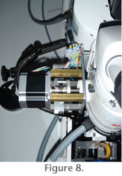 In earlier versions of AMOR an unfavorably high magnification during tilting sometimes caused a specimen to leave the imaging frame on the monitor, which means loss of control of the specimen. In such a case AMOR interrupted positioning. In order to avoid such situations the zoom-knob of the magnification body of the microscope was motorized and integrated into the AMOR program (Figure 8), and specimens are automatically re-centered with respect to the imaging window if necessary. In earlier versions of AMOR an unfavorably high magnification during tilting sometimes caused a specimen to leave the imaging frame on the monitor, which means loss of control of the specimen. In such a case AMOR interrupted positioning. In order to avoid such situations the zoom-knob of the magnification body of the microscope was motorized and integrated into the AMOR program (Figure 8), and specimens are automatically re-centered with respect to the imaging window if necessary.
There exist few motorized zoom motors on the market (for example from
www.asiimaging.com), but they were not compatible to our Leica MZ6 geometry without major modifications. For this reason an automated zoom was designed and programmed in LabView. A two-phase stepping motor (model CSK266-AT from Orientalmotor GmbH, resolution 1.8° at full-step) was found to fulfill the requirements, which is connected with the AX stand of the microscope. The connection between motor-axis and zoom-drive of the microscope is created with a flexible coupling (Toolflex) from KTR (KTR-Kupplungstechnik AG in Zürich). The electronics for the automated zoom-control is housed in a second external "Zoom-Box", which is fed by a second motion control card in the PC. This extra PCI card was necessary because the first card for moving the stage axes could not handle more than four axes. For a full zooming cycle, i.e., from 0.63x through 4.00x the motor uses about 200 steps. Two electrical push-button switches are attached on either side of the zoom-axis in order to stop zooming at the lower and upper end of the zoom range. Because the magnification per motor increment increases following an exponential law (see Supplement #6 in
Knappertsbusch 2004), the sensitivity is greatest at the higher-end of the magnification range.
Only through addition of this motorized zoom to the system it is now possible to sequentially scan all fields of the slide and automatically orientate all specimens in the slide. The motor-zoom can be software enabled or disabled during initialization of AMOR, which maintains the functionality of the tilting stage under manual zoom operation in case the motorized zoom fails.
System Integration and Orientation Control
System integration of AMOR was achieved with LabView 8.5 from National Instruments, a graphical software development environment common in industry for machine vision and motion applications. The program (also called AMOR) consists of a logical sequence of so-called VIs (virtual instruments), which are factory designed routines and functions to solve a special task like generation of a standard input current signal to drive a stepping motor. Orientation control of microfossils was achieved by using the VIs of NI-Vision module of LabView. AMOR can be used to orient a disk-shaped foraminifer like Globorotalia menardii in two basic positions: Keel-view and umbilical or spiral view. In the keel position, the specimen "stands" on its periphery with the primary aperture facing upward. In the umbilical or spiral position the umbilical or spiral side is facing upward, respectively. Before application specimens must be fixed in an approximately oriented position, which needs to be done manually using some water soluble glue under a binocular microscope.
The coordinate system of AMOR is Cartesian and refers to the rectangular grid-lines drawn on the slide: X denotes the translation to the left or right, Y denotes the translation in perpendicular direction in the plane of the slide. On the computer monitor these movements correspond to image translations in left/right directions and up/down directions, respectively. Tilting follows a similar scheme: Roll causes movement of a specimen on the computer monitor in direction of the X axis (i.e., left, right), and pitch causes movement of a specimen on the monitor in direction of the Yaxis (up and down, see
Figure 7.3).
The perfect orientation of the shell in keel view is attained when the following three conditions are met (Figure 7.3). (1) The enclosing area of the test during tilting about the roll-axis is minimal ["roll condition"]. (2) The longest axis in keel view during tilt about the pitch-axis reaches a maximum. This pitch-condition is necessary in order to keep the apertural face of globorotalid shells in upward position, which functions well in the case of menardiform globorotalids, our main study object. (3) The longest axis in keel view is vertical in the imaging window ["rotational condition"]. While pitch- and roll-conditions are achieved through physical specimen tilting and real-time image calculation of area and length measurement, the rotational condition is achieved through soft-image rotation with the function "Autorotate" (see further below). These conditions were evaluated through experimentation. For other foraminiferal species the ideal conditions for positioning must first be defined and tested. Orientation in umbilical or spiral view of the test is easier because then the perfect position is attained when the surface area of the shell reaches a maximum.
Autofocussing
Autofocussing is a prerequisite for automated object orientation. Two ways for obtaining a focused image were implemented: A coarse focus selects for the highest variance within an active region of interest (ROI) of the image. A well-focused image has many details with many grey-levels in a narrow area and hence shows a high variance. This method worked well at lower magnifications, where the depth of field of the parfocal zoom-lens system of the Leica MZ6 is quite wide. A parfocal microscope objective stays in focus when magnification is changed from a higher power objective to a lower power objective. At higher magnifications, when incident light becomes more attenuated and the narrower depth of focus causes less strong local variances, a different algorithm (fine focus) was implemented. This is a minimizing function for the surface area of the object at perfect focus conditions. It is based on our observation that at higher magnifications a bright object appears in focus as soon as its surface area (defined by the area inside of the periphery of the particle) becomes minimal. When the object moves out of focus ("under- or overfocus") the surface area increases continuously before it fades away.
Autorotate
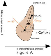 Autorotate applies to shells in keel view and is a software function to rotate the silhouette of the shell into vertical orientation (i.e., with the largest axis being parallel to the vertical side of the imaging window). This step is necessary for later outline analysis of the shells. In AMOR vertical orientation is achieved by minimizing the momentum of inertia of the thresholded particle (see
Figure 9). This method is applicable here because specimens are manually pre-oriented in the slide in north-south orientation as much as possible. For ideal orientation of the specimen function Autorotate then requires only a small amount of rotation of the image (usually less than about 5 degrees, depending on how well the specimens were placed north-south in the slide). Autorotate applies to shells in keel view and is a software function to rotate the silhouette of the shell into vertical orientation (i.e., with the largest axis being parallel to the vertical side of the imaging window). This step is necessary for later outline analysis of the shells. In AMOR vertical orientation is achieved by minimizing the momentum of inertia of the thresholded particle (see
Figure 9). This method is applicable here because specimens are manually pre-oriented in the slide in north-south orientation as much as possible. For ideal orientation of the specimen function Autorotate then requires only a small amount of rotation of the image (usually less than about 5 degrees, depending on how well the specimens were placed north-south in the slide).
Slide Calibration
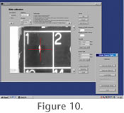 Experience has shown that there is some variability in position and size of the array of grid fields in commercially available faunal slides, even if they come from the same manufacturer. Without correction, this variation prohibits reliable automated positioning. In order to avoid this difficulty, a special slide calibration function was implemented in AMOR3 (Widmer 2008). This function enables the user to assign the characteristics of a particular slide to an external file (see
Figure 10). These characteristics include the number of columns and rows of fields of the gridded slide and the center coordinates of the first and last fields in the slide. This information can later be re-loaded into the memory of the program, if needed. In this manner, any kind of gridded faunal slides with standard dimensions of 75 mm x 25 mm (=size of the cardboard), but independent of the number of engraved fields, can be applied. Experience has shown that there is some variability in position and size of the array of grid fields in commercially available faunal slides, even if they come from the same manufacturer. Without correction, this variation prohibits reliable automated positioning. In order to avoid this difficulty, a special slide calibration function was implemented in AMOR3 (Widmer 2008). This function enables the user to assign the characteristics of a particular slide to an external file (see
Figure 10). These characteristics include the number of columns and rows of fields of the gridded slide and the center coordinates of the first and last fields in the slide. This information can later be re-loaded into the memory of the program, if needed. In this manner, any kind of gridded faunal slides with standard dimensions of 75 mm x 25 mm (=size of the cardboard), but independent of the number of engraved fields, can be applied.
Autocharacter Function
Another difficulty with earlier versions of AMOR was that occasionally the white numbers that are engraved in each field of a faunal slide were mistaken as a microfossil. Such misidentification led to failure during automated orientation. In version 3 of AMOR this difficulty was remedied through implementation of a character recognition and blending function (Widmer 2008).
The fix was possible using character recognition algorithms embedded in the library of LabView's Vision module. With AMOR3 the user is also no longer confronted with the additional problem, that in some faunal slides the numbering is located in the upper left corner of each square (such as in slides with 60 fields) while in other types the numbering sits in the lower right corner of each square (for example in faunal slides with 36 fields). In this way the frequency of microfossil misinterpretation could be reduced to about one failure per 100 fields.
|