|
|
|
|
|
|
||||||||||||||||||||||||
|
|
Material and Methods
|
| AMNH | American Museum of Natural History, New York, USA | |
| BSP | Bayrische Staatssammlung für Paläontologie und Geologie, München, Germany (formerly Bayrische Staatssammlung für Paläontologie und historische Geologie) | |
| GPIT | see IFGT | |
| IFGT |
Institute for Geosciences, Eberhard-Karls-Universität Tübingen, Tübingen, Germany (also IFG or UT in the literature) Formerly Geologisch-Paläontologisches Institut Tübingen (abbreviated GPIT) |
|
| MB.R. | see MFN | |
| MFN | Museum für Naturkunde Leibniz-Institut für Evolutions- und
Biodiversitätsforschung an der Humboldt-Universität zu Berlin Formerly Museum für Naturkunde der Humboldt-Universität zu Berlin Also abbreviated MNHB. Collection numbers are MB.R.####. |
|
| MNHB | see MFN | |
| MSF | Sauriermuseum Frick, Frick, Switzerland |
Computer programs
Extraction of the bone surface shapes was performed in a time-limited trial version of AMIRA 3.11® by AMIRA Corp. CAD tasks (mounting the skeleton, CAD model creation) were conducted using McNeel Associates Inc. 'Rhinoceros® 3.0 NURBS modeling for Windows®' and 'Rhinoceros® 4.0 NURBS modeling for Windows®'. For polygon mesh editing I used a time-limited trial version of 'Geomagic Qualify 8.0®' from Geomagic Inc.CAE models were created and assessed in MSC.visualNastran 4D® by MSC Corp. and NX5® by Siemens PLM Software.
3D file extraction
The bones of GPIT1 were CT-scanned by B. Ludescher at the University Hospital of the Eberhard-Karls-University Tübingen on a SiemensTM Somatom Sensation© scanner. Slice thickness was 0.5 mm, with a 0.5 mm increment and a 0.25 mm overlap. The surface shapes of the bones were extracted from the resulting DICOM-format slice graphics using AMIRA® 3.11 and saved as polygon meshes in stereolithography format (*.stl). This created artifacts (massive wrinkling of the surfaces), and a reduced set of every second slice was instead used. This removed overlap between neighboring slices and eliminated the artifacts. Internal surfaces and artifacts were removed, and the files were reduced in size to about 25% of original size using Geomagic Qualify 8.0®. Large (girdle and limb) bones were further reduced in size, to save computing time.
Mounting the virtual skeleton
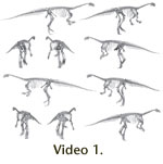
The bones were mounted in Rhinoceros® 3.0 and 4.0. The limbs were articulated separately from the vertebral column and girdle elements, and the partial assemblages later combined to create the two basic postures (bipedal and quadrupedal) and their variations.
The vertebral column was placed into near-neutral articulation (ostgeologically neutral pose [ONP], see Stevens and Parrish 1999) three separate times, with several weeks pause between the digital mountings, in order to avoid one mounting influencing decisions in the next mounting. In each case, the vertebrae were articulated with each other in pairs, so that only the last added vertebra and the one currently being placed were visible, to avoid errors in placement caused by apparent curvatures of the entire column. Two instances were created by proceeding along the vertebral column vertebra by vertebra, once from the front and once from the tail tip. The third mount was created in pieces, with the cervicals, dorsals, and caudals articulated separately and then combined in a final step. This redundancy in mounting was intended to remove bias caused by preconceived notions as far as possible. Neutral pose was determined by placing the anterior and posterior surfaces of the centra as parallel as possible while guaranteeing maximal overlap of the zygapophyses. Because nearly all dorsals in GPIT1 are distorted, with the transverse processes and zygapophyses rotated dorsally on the right and ventrally on the left side, and some show signs of slight antero-posterior compaction, neutral pose had to be approximated as a best guess in some of the articulations. However, comparison with other Plateosaurus material (SMNS 13200, GPIT2, SMNS F33) indicates that the induced errors are probably smaller than differences caused by intraspecific variation. All three digital mounts show highly similar curvatures and total lengths of the assembled spine, so only one was used in all further analyses. All differences were significantly smaller than even extremely conservative assessments of the range of motion in the intervertebral joints, and did not influence the overall trends in the spine. The limbs were also mounted repeatedly.
The bipedal and quadrupedal postures were created based solely on the osteology and poses suggested in the literature, even if the latter demanded impossible joint articulations. The expected position of the COM was not taken into account to avoid bias. The bipedal and quadrupedal poses resembled published reconstructions (Galton 1990, 2000; Paul 1987, 1997; Wellnhofer 1994; Weishampel and Westphal 1986), without regard for joint limits, center of mass, or other considerations.
3D model creation
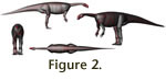 Rhinoceros® 3.0 and 4.0 were used to create NURBS bodies for a 3D model for the
living animal (Figure 2). Initially it consisted of ellipsoid bodies that were
deformed to approximate the 3D shape defined by the extents of the skeleton.
Then, the 3D bodies were further enlarged to incorporate room for soft tissues.
This method differs from the ellipses-based method of
Henderson (1999), allowing
non-elliptical cross sections. The amount of soft tissue is conservative, except
for the hips and upper hindlimbs. Here, relatively ample amounts of muscles were
assumed, because dinosaurs produce most of the posteriorly directed force
required for rapid locomotion not by limb extension, but by limb retraction (see
Gatesy 1990), in contrast to mammals. Therefore, the iliofemoral, ischiofemoral,
and especially caudofemoral musculature must have been relatively stronger than
in mammals. The recent discovery of a hadrosaur mummy in North Dakota (US)
confirms that at least hadrosaurs possessed much more musculature in the upper
hindlimbs and tail than most previous reconstructions assumed (National
Geographic Society 2007, Dec. 12). Since the musculoskeletal system of the all
non-avian dinosaurs is relatively uniform, I feel that a robust soft tissue
reconstruction of the hindlimb and basal tail of Plateosaurus is
reasonable. Additional evidence comes from extant crocodilians.
Persons (2009)
found that all of the many extant taxa used for his study had a far larger
amount of tail musculature than is usually assumed to be present in dinosaurs.
Specifically, the muscle cross sections protrude far beyond the tips of the
haemal arches and transverse processes (Persons 2009).
Rhinoceros® 3.0 and 4.0 were used to create NURBS bodies for a 3D model for the
living animal (Figure 2). Initially it consisted of ellipsoid bodies that were
deformed to approximate the 3D shape defined by the extents of the skeleton.
Then, the 3D bodies were further enlarged to incorporate room for soft tissues.
This method differs from the ellipses-based method of
Henderson (1999), allowing
non-elliptical cross sections. The amount of soft tissue is conservative, except
for the hips and upper hindlimbs. Here, relatively ample amounts of muscles were
assumed, because dinosaurs produce most of the posteriorly directed force
required for rapid locomotion not by limb extension, but by limb retraction (see
Gatesy 1990), in contrast to mammals. Therefore, the iliofemoral, ischiofemoral,
and especially caudofemoral musculature must have been relatively stronger than
in mammals. The recent discovery of a hadrosaur mummy in North Dakota (US)
confirms that at least hadrosaurs possessed much more musculature in the upper
hindlimbs and tail than most previous reconstructions assumed (National
Geographic Society 2007, Dec. 12). Since the musculoskeletal system of the all
non-avian dinosaurs is relatively uniform, I feel that a robust soft tissue
reconstruction of the hindlimb and basal tail of Plateosaurus is
reasonable. Additional evidence comes from extant crocodilians.
Persons (2009)
found that all of the many extant taxa used for his study had a far larger
amount of tail musculature than is usually assumed to be present in dinosaurs.
Specifically, the muscle cross sections protrude far beyond the tips of the
haemal arches and transverse processes (Persons 2009).
The model's limbs were sectioned into functional units (manus, antebrachium, etc.), while the neck, body, and tail were sectioned vertically into slices. Each part was thus turned into a separate entity, so that it could be given an individual density value. Theoretically, it would have been possible to subtract the bones from these volumes and give the remaining 3D bodies the average density of soft tissues. However, the gain in accuracy would have been minimal, especially given the uncertainty considering the amount of soft tissues, and the calculation demands for the computer programs would have increased massively.
CAE assessment of mass distribution
The center of mass (COM) was determined in a computer-aided engineering (CAE) software using NASTRAN. NASTRAN is a finite element analysis solver originally developed by NASA and today available in several versions able to handle kinetic/dynamic modeling of rigid body systems. Problems are time-discretized in NASTRAN, which solves them using the simple Euler integration, or the more complex and thus computer calculation time intensive Kutta-Merson integration. The latter allows a variable number of repeated integrations per (pre-defined) time step, and attempts to estimate the integration error. Thus, it delivers significantly more accurate results for highly unequal mass or speed combinations in the model (see Fox 1962 for details on the integration methods). For quasi-static analysis as presented here (i.e., standing models of Plateosaurus used to determine the position of the COM), Euler integration is sufficient. Tests using both methods on the same file failed to show differences in the results. The exact position of the COM was calculated in the program.